
Design Conditions for Data Through a 5 Pin Magnetic Cable
Published on September 11, 2026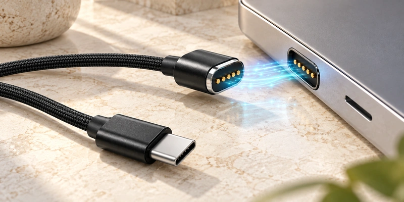
- Conditions for Five-Contact Data Transfer
- Possible Assignments
- The Complete Electrical Channel
- USB-C and USB Data Capability
- Factors in Signal Reliability
- Specifying Power and Data Together
A five-contact magnetic cable can carry power and data together if its map, wiring, signal type, contact design and device circuit support them. Contact count alone proves neither function. Assign the available paths to power, ground, data, detection or other signals as the device requires.
5 pin magnetic charging cableConditions for Five-Contact Data Transfer
A five-contact assembly can be developed for simultaneous charging and communication.
Five pins describes the available paths, not their functions. Some may carry supply and ground, with others assigned to data, identification or control by the circuit design.
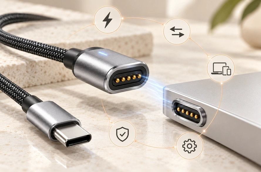
For example, two paths can carry power, two a signal pair and one identification. Another circuit can use a different map, so cable and device must be designed together for the intended data function.
Magtor can configure the five-contact cable's map, USB-A or USB-C end and mating arrangement around the customer's circuit.
MagtorPossible Assignments
There is no universal five-contact pogo cable pinout. Define each path from the device's electrical requirements.
| Example Design | Possible Pin Functions |
|---|---|
| Charging only | V+, GND and additional power or detection contacts |
| Charging + data | V+, GND, Data+, Data−, ID |
| Charging + detection | V+, GND, ID, Detect, Control |
| Higher-current design | Multiple power/ground paths + signal |
| Custom interface | Five project-specific power or signal functions |
Scroll horizontally to view every column.
These are examples. Use the approved schematic and wiring drawing for the actual assignment.
Similar-looking five-contact heads may still have incompatible electrical layouts.
The Complete Electrical Channel
Each pogo contact conducts between a cable path and its matching device contact, as in other electrical interconnects. The magnetic parts position the interface rather than establishing the protocol.
Connecting two signal paths alone is insufficient to establish stable communication.
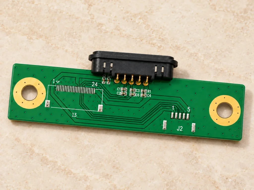
The channel includes the PCB, pads, pogo pins, head termination, internal conductors and opposite end connector. For faster signals, assess conductor layout, ground return, shielding, length and connector transitions together.
Assess the magnetic head within that complete channel instead of evaluating it in isolation.
Review a data-oriented Magnetic Cable Connector alongside its cable construction and device PCB.
Magnetic Cable ConnectorUSB-C and USB Data Capability
A Type-C end alone cannot establish data support.
Type-C may be the source or host connection, while a separate contact map and electrical implementation define the magnetic end.
A compatible Type-C system can implement power and data, and USB Power Delivery can coexist with data where supported. The magnetic assembly still needs suitable wiring, assignments and electronics for the intended USB functions.
USB Type-COne design might use Type-C only as its supply input and assign the five contacts to charging and detection. Another can route an appropriate pair through the magnetic head for communication.
The design reminder is:
A USB-C plug does not guarantee USB data through the magnetic cable.
Confirm protocol and wiring while developing the assembly.
Factors in Signal Reliability
First match the signal, ground and power assignments between cable and device.
Resistance and working compression matter too. Low pressure, contamination or wear can raise resistance or make contact intermittent.
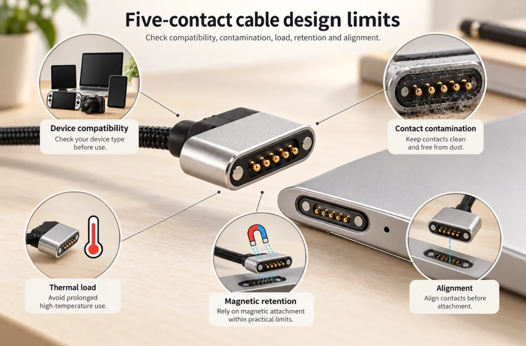
As signal demands rise, length, conductor arrangement, shielding and return-path design become more important. Validate protocol and data performance across the complete cable-to-device channel rather than inferring them from contact count.
Wearable and outdoor contacts may face sweat, moisture and deposits. Select materials and plating to limit corrosion-related resistance changes. Magtor can assess multilayer finishes for sweat and electrochemical exposure, with effectiveness validated for the selected structure and conditions.
Retention and alignment should hold contacts at the specified working position. Strong magnets cannot ensure electrical stability where the geometry lets pins move off their pads.
Specifying Power and Data Together
Begin with the circuit requirements rather than the cable's appearance or contact count.
Before samples, define voltage and current, signal type or protocol, assignments, pitch, length, gauge, USB-A/USB-C/bare-wire end, magnetic polarity, electrical polarity, working compression, dimensions and environmental protection.
Review the housing and PCB to set orientation and mating area, and choose whether a 90° or 180° outlet fits the route.
Magtor can configure the pin map, cable specification, USB-A, USB-C or bare-wire end and outlet direction of a five-contact assembly for OEM integration.
Validating the Device and Cable Together
A five-contact magnetic cable can transfer data when the implementation supports it; its count does not define a communication function.
Coordinate the contact map, electrical needs, protocol, cable construction and PCB layout for charging and communication.
Five paths offer more allocation choices than a simple two-contact charging interface for data, identification or control. Validate the final assembly with the actual device before mass production.
Questions About Five-Contact Data Cables
Are all five-contact magnetic cables compatible?
No. Pitch, assignments, electrical polarity, magnetic polarity, dimensions, voltage and current may differ.
Can power and signals cross together?
They can with appropriate assignments: some paths carry power, while others carry data, detection, identification or control supported by the electronics.
Is there a universal five-contact pinout?
No. Magnetic pogo assignments are usually defined for the device, rather than inferred from a standardized USB connector map.
Is matching head shape enough for replacement?
No. Five contacts in a similar head still require matching maps and electrical specifications, as well as mechanical fit.
Can a custom assembly use USB-A or USB-C?
Yes. Choose USB-A, USB-C, bare wire, terminals or another custom end according to the device and system design; the end shape does not determine its data function.