
Data Through a 4 Pin Magnetic Cable: Design Requirements
Published on September 10, 2026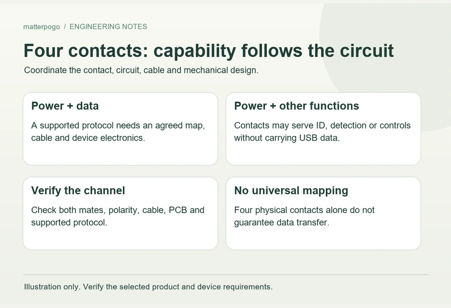
- Conditions for Four-Contact Data Transfer
- Assigning Contact Functions
- Signals and Communication Protocols
- Why Four Contacts May Provide Charging Only
- Verifying Data Capability
- OEM Requirements for Power and Data
A four-contact magnetic cable can carry data when the pin map, conductors, contacts and device electronics implement the required communication path. Four visible contacts alone do not establish data capability.
4 pin magnetic charging cableConditions for Four-Contact Data Transfer
Power and data can share four contacts when two carry supply and ground and the other two carry suitable signals, with both ends designed for that arrangement.
One possible USB 2.0-style map is:
| Contact | Possible Function |
|---|---|
| Pin 1 | VBUS |
| Pin 2 | GND |
| Pin 3 | D+ |
| Pin 4 | D− |
Scroll horizontally to view every column.
A four-contact magnetic interface wired to power, ground, D+ and D− can form part of a USB power-and-data design when the complete system supports it. A structural image alone does not establish those connections or validated data performance.
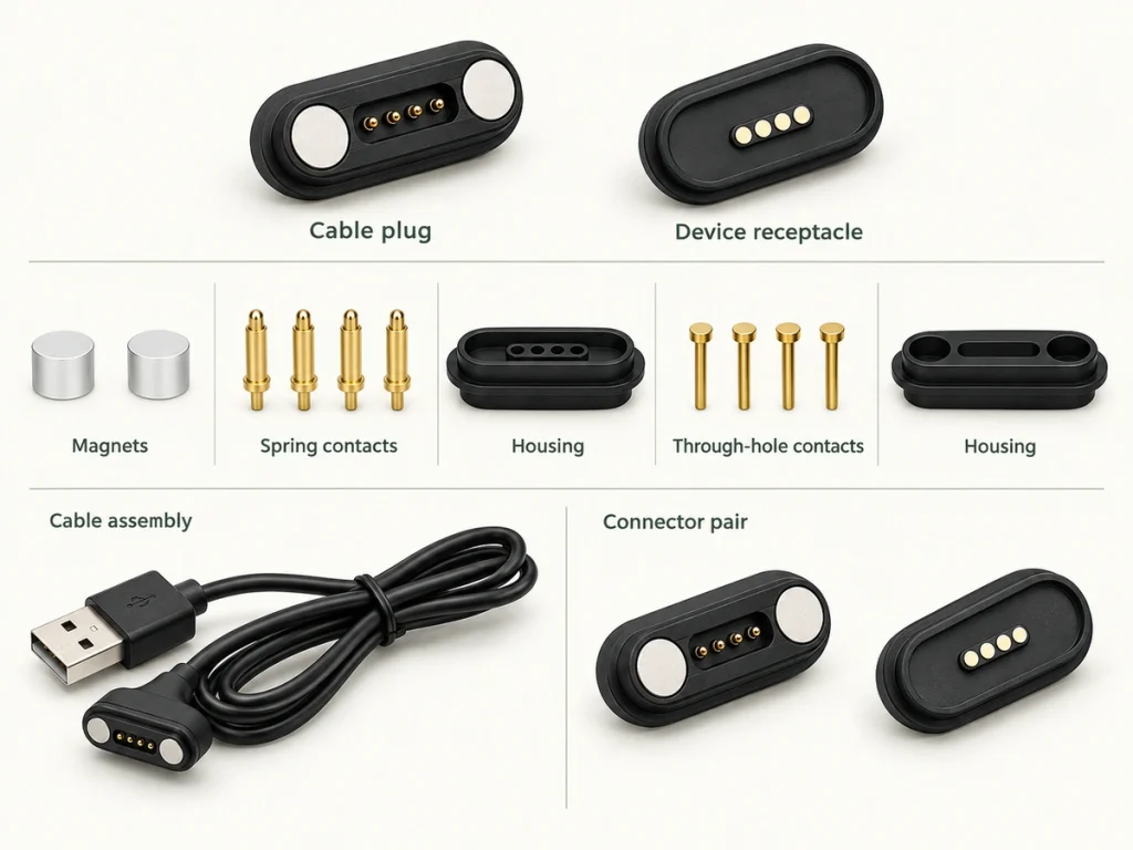
Treat that map as an example. Magnetic four-contact cables have no universal assignment.
Magtor can configure a four-contact assembly from the device circuit and interface requirements rather than applying one sequence to all designs.
Assigning Contact Functions
The device design determines which function each path serves.
One map may use VBUS, GND, D+ and D−; another V+, GND, ID and detection. Two custom signal paths or additional power and ground contacts are also possible where the architecture calls for them, with current sharing and thermal limits assessed for parallel paths.
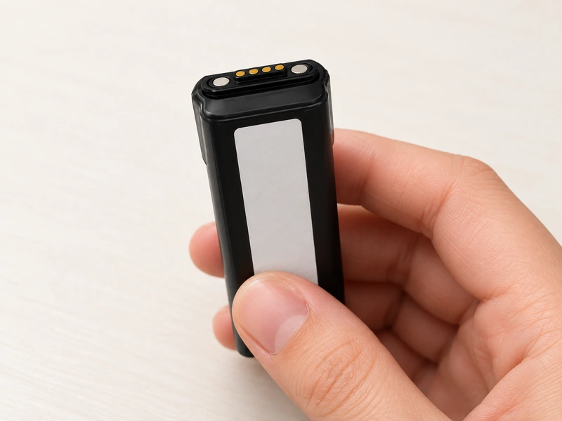
The contact-count label means:
Four electrical paths are available; their communication roles remain to be defined.
A typical option in the Magtor Magnetic Cable Connector range assigns power, ground and two configurable signals. Confirm the final map before producing samples.
Magnetic Cable ConnectorReview assignment, polarity, pitch, voltage, current, signal needs and orientation alongside contact count.
Signals and Communication Protocols
Contacts provide conductive paths, while electronics at the source and device define the protocol and use of those paths.
A four-path USB 2.0 design may carry VBUS, GND, D+ and D−. USB-IF maintains the USB 2.0 specification and compliance requirements; the complete implementation must address the applicable requirements.
USB 2.0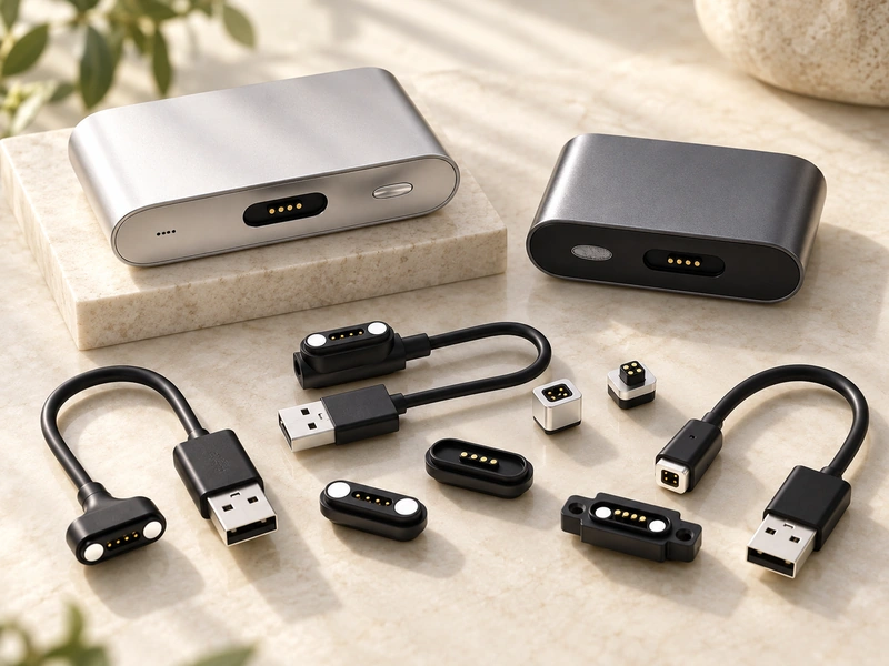
Other assigned signals need not be USB.
Possible functions include ID, charging detection, accessory recognition, sensing, control or another device-defined signal.
For example, a wearable may charge through two paths and identify its accessory through another. A docked industrial device may instead need communication or control paths.
Ask what 'signal transmission' means in the product specification. It does not necessarily mean USB data.
Why Four Contacts May Provide Charging Only
A four-contact magnetic head may have no USB data connection.
Its third and fourth paths might serve ID, detection or control instead of D+ and D−.
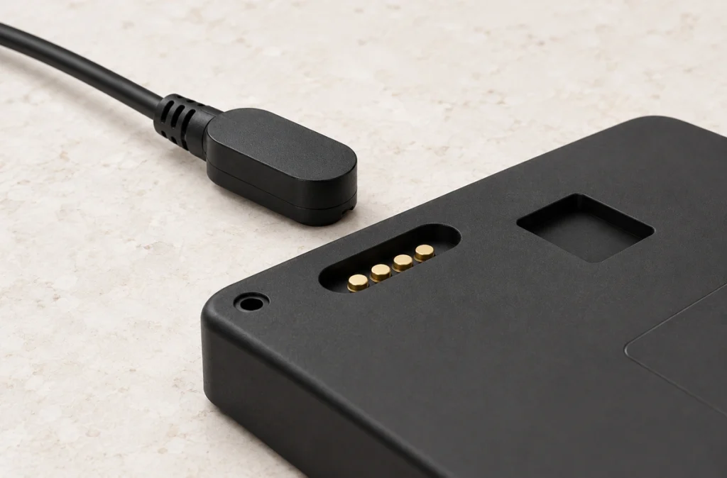
Cable construction is another factor. Contacts visible at the head may not be connected to USB data terminals at the source end.
The source-end shape is therefore insufficient:
A USB-C plug does not prove a data path through the assembly.
Projects using Type-C can have different requirements, from fuller USB functions to USB 2.0 communication or charging alone. USB-IF lists Type-C Cable and Connector Specification Release 2.5 dated 8 April 2026; use its applicable requirements when specifying the implemented interface.
USB Type-CNeither the Type-C plug nor four magnetic contacts independently establishes data support.
Verifying Data Capability
Start by reviewing the contact map and wiring drawing.
For USB 2.0, verify that the intended data conductors run through the cable and reach the correct terminals at both ends. The name 'four-contact magnetic cable' is not sufficient.
Check the device circuit as well. Data conductors need matching assignments and the corresponding communication electronics at the mating end.
Mechanical and electrical fit also includes pitch, contact order, magnetic polarity, mating direction, housing dimensions and electrical polarity.
Do not assume similar-looking heads are interchangeable.
Reviewing the PCB and connector drawings before samples can reveal reversed polarity, misplaced signals and incompatible geometry.
OEM Requirements for Power and Data
Specify the required electrical functions before asking for a four-contact connector.
Identify power, ground and communication paths in the drawing. For USB 2.0, design and validate the complete interface against the relevant electrical requirements; simple continuity on D+ and D− cannot establish performance.
Length, conductor structure, shielding, resistance, working height and mechanical contact stability all affect the assembled interface.
Magtor can configure assignments, pitch, USB-A, USB-C or bare-wire ends, length, outlet direction, magnet polarity and mechanical structure to suit the device.
MagtorBefore samples, provide voltage, current, communication needs, contact definitions, PCB or enclosure drawings, installation space, end connector, length and environment.
These requirements allow development of a matched cable-and-device interface instead of selection from contact count alone.
Confirming the Complete Data Path
Data transfer is possible in a four-contact magnetic assembly designed for it; the count itself is not evidence of support.
VBUS, GND, D+ and D− are one possible data-oriented map. Other designs use the additional paths for ID, charging control or custom signals.
Confirm the map, internal wiring, communication requirements, polarity and device circuitry before choosing the cable.
Defining these inputs first helps decide whether an OEM assembly needs charging alone or integrated charging and communication.