
Two-contact Magnetic Interfaces: Practical Benefits
Published on July 15, 2026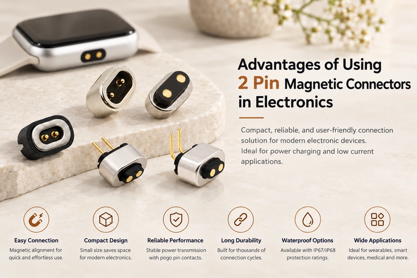
- The Two-contact Magnetic Arrangement
- Potential Integration Benefits
- Application Examples
- Selection Requirements
A two-contact magnetic interface can provide a compact power connection with guided attachment and spring-contact engagement. It is an option for wearables, smart-home products, medical equipment and portable devices when its load, exposure and life requirements are satisfied. This guide explains the potential benefits and selection conditions.
two-contact magnetic connectorsThe Two-contact Magnetic Arrangement
Two conductive paths carry the assigned electrical function, commonly supply and return for charging. Magnets guide and retain the mating faces, while the contact system establishes conduction.
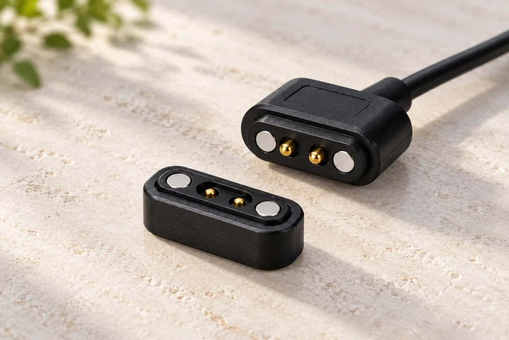
Instead of inserting a conventional plug into a socket, the intended magnetic halves approach and locate against one another. Stable engagement depends on the magnet arrangement, locating geometry and contact compression across the permitted tolerances.
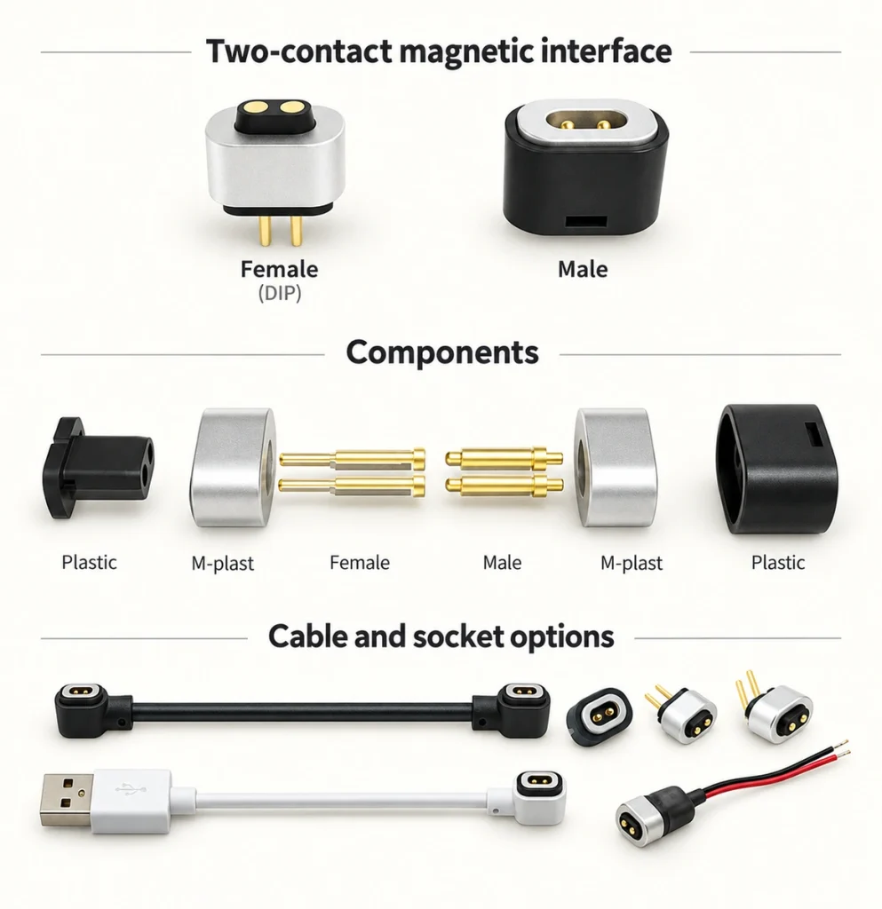
magnetic connectorsThe principal components may include:
Pogo contacts — spring-loaded conductive paths with defined travel and force.
Permanent magnets — guidance and retention for the intended mating geometry.
A housing — locating and support for the internal components.
Potential Integration Benefits
1. Quick Guided Attachment
Convenient repeated attachment is a practical reason to consider a two-contact magnetic interface.
Magnets can reduce the alignment effort and avoid insertion into a port. Users still need the intended orientation and approach range, while spring contacts require their working compression. Validate those actions in the actual device.
Application examples include:
Smart wearables.
Wireless earbuds.
Smartwatches.
Portable medical devices.
Smart-home products.
A suitable locating structure can make operation easier and limit mis-mating damage. Confirm that benefit with the intended product and users.
2. Compact Integration
Small electronic products need a contact arrangement that meets their space constraints without losing required performance.
The dimension comparison discussed here uses about 8mm for a conventional USB arrangement and about 4mm for a possible pogo-contact arrangement. Those are illustrative geometry examples, not dimensions for every USB or magnetic product. Compare drawings in the same direction and include the housing, support and PCB clearances when assessing space savings.
USBPossible compact applications include fitness trackers, smart glasses, Bluetooth devices, miniature sensors and portable instruments.
3. A Defined Electrical Contact System
A correctly specified pogo-contact system can maintain engagement through its permitted working travel and tolerance range.
Spring compliance can help keep contact pressure consistent, while materials, coating and alignment influence resistance and vibration behavior. Different designs serve different current requirements. Measure loaded performance and relevant life tests instead of assuming that every pogo interface outperforms fixed contacts.
4. Repeated-mating Design
Conventional insertion interfaces can experience wear as their mating parts slide and retain the plug. Magnetic face contacts use a different engagement method, with their own compression and surface movement.
A face-contact arrangement may reduce some insertion friction and related loads. It still experiences contact wear, so compare the exact assembly’s cycle testing and permitted performance change rather than claiming that magnetic contacts automatically last longer than USB.
5. A Controlled Breakaway Response
A magnetic arrangement may be designed to release under a specified pull load.
Validate the release force and direction against the device’s normal handling and foreseeable cable pulls. A suitable response can reduce loads transmitted to the port or mounting.
The design may help limit:
Bent connector structures.
Cable damage.
Pull-related falls from a surface.
Stress transferred to internal parts.
This can be useful in wearables, office equipment and home electronics, but it does not guarantee prevention of every damage or safety incident.
6. Sealing Options
A device-side interface may use O-rings, compatible adhesive or a molded sealing structure to target IP65, IP67 or IP68. The rating depends on testing the relevant protected parts and assembly state, not merely adding one of those sealing features.
IP65, IP67 or IP68Application examples include:
Smartwatches.
Outdoor equipment.
Medical devices with the required qualification.
Smart pet trackers.
Portable electronics.
A validated seal limits the specified water and dust ingress. Corrosion exposure and any accessible live contacts require separate review; an IP result does not prove resistance to every contaminant.
Application Examples
Wearables
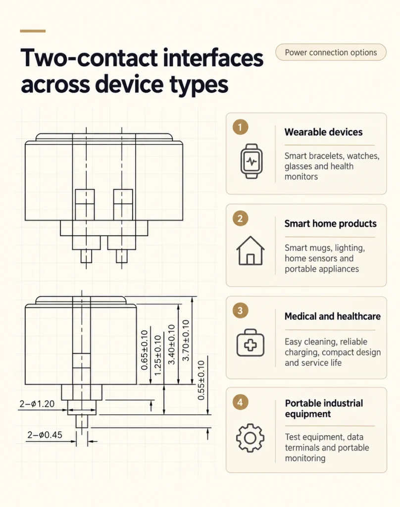
Smart bands, smartwatches, smart glasses and health-monitoring products may need a compact, low-mass charging face. A two-contact arrangement can be considered when the power paths and product qualification requirements fit the design.
Smart-home Products
Smart coffee cups, lighting, home sensors and portable appliances are examples where a compact magnetic power interface may be useful. Define the actual electrical and exposure conditions for each product.
Medical and Healthcare Products
Medical applications need the specified electrical stability and hygiene process. An accessible pogo-contact arrangement may support cleaning and maintenance, but compactness, life and disinfectant compatibility require evidence for the actual device and interface.
Industrial Portable Equipment
Portable test equipment, data terminals and monitoring instruments may encounter harsh use. Choose and validate the contact, sealing and support arrangement against their current, vibration and environmental requirements.
Selection Requirements
Review these inputs before choosing a two-contact interface:
1. Current and Voltage
Specify the actual charging load, voltage, transients and relevant electrical limits.
2. Dimensions and Mounting
Check available PCB and enclosure space, then choose an appropriate surface-mount, cable or custom mounting structure.
3. Exposure Protection
Select sealing and corrosion performance for the actual outdoor or industrial environment, with the relevant protection state and test evidence.
4. Mating Life
Define the expected connection frequency and service period, then validate the chosen assembly’s durability.
5. Customization
A particular product may need changes to magnetic force, contact arrangement, dimensions or cable assembly. Review manufacturing and testing requirements for those changes.
Conclusion
A two-contact magnetic interface can combine convenient guidance with a compact power path and an appropriate sealing arrangement. Contact stability and service life depend on the actual assembly. Compare those requirements when considering it for wearables, smart-home, medical or industrial products.
Share the load, mounting, exposure and life target with Magtor to discuss a suitable connector arrangement. A standard or custom design should be selected against those requirements and supported by the relevant validation evidence.
Magtor