
Mixed Power and Signal Magnetic Connectors for Robotics
Published on July 23, 2026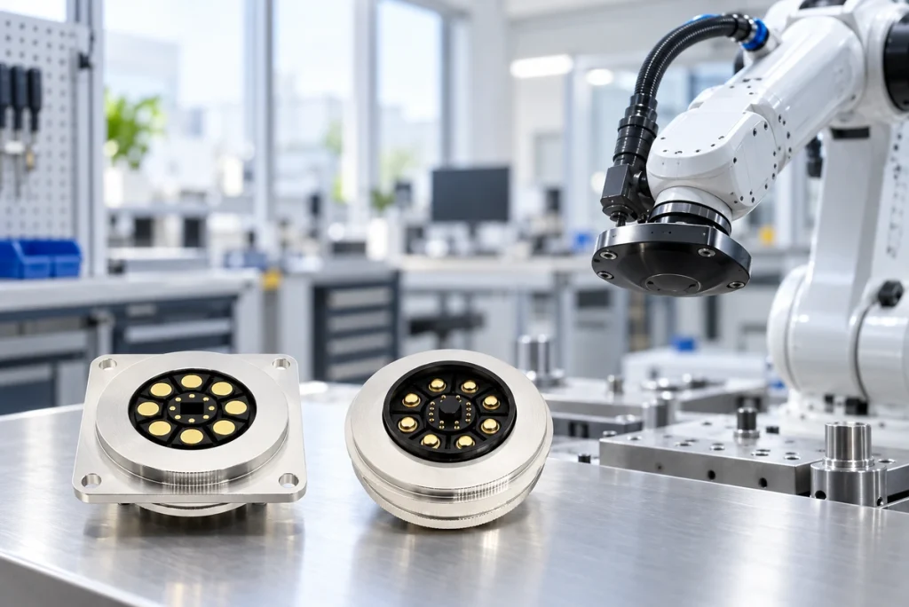
- Power-connection Requirements in Robotics
- Combining Larger Power Contacts and Smaller Signal Contacts
- Cost Considerations for a Mixed-contact Design
- Potential Benefits in Robotic Equipment
- Selecting the Assembly for a Robot
A mixed-contact magnetic interface can provide power and supported signals in one assembly. Larger power contacts and smaller signal contacts may help match the different electrical requirements of AGVs, robotic arms and automation equipment. Evaluate current, communication integrity, packaging and cost together rather than assuming one design improves every system.
Higher-current magnetic interfacesPower-connection Requirements in Robotics
Robots can combine motors, actuators, battery modules, sensors and control units. Their connections need the appropriate power paths and dependable communication between modules, with requirements defined for the complete operating cycle.

An unstable connection can cause voltage drop, interrupted signals, excess heat or unplanned downtime. Assess contact performance under the robot’s actual vibration, repeated docking and industrial exposure conditions.
A magnetic spring-contact assembly can guide attachment and accommodate limited movement through contact compliance. Reliable engagement still depends on retention, locating geometry, spring travel and pressure, and must be verified under the specified vibration and loads.
Combining Larger Power Contacts and Smaller Signal Contacts
A mixed-size contact allocation is one approach to combining different electrical functions in a robotic interface.
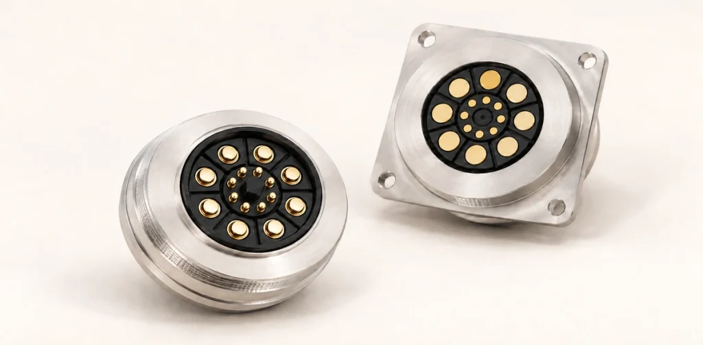
Size each contact for its assigned function rather than making every position identical. Larger conductive paths may reduce resistance for motor, battery or power-module loads when the complete thermal design is suitable. Smaller contacts may carry lower-current functions such as CAN, UART, sensor feedback and control signals, provided their allocation and signal integrity are validated.
CAN communicationThis arrangement can combine power and communication in one connector, with the footprint determined by contact spacing, insulation, retention and the required ratings.
For example, a 16-contact robotic assembly may allocate several larger paths to motor or battery power and the remaining smaller paths to data and control. Define the supply and return paths, current limits and supported protocols for that exact allocation; the contact count alone does not establish performance.
Cost Considerations for a Mixed-contact Design
Using a large power contact at every position may add material, manufacturing work and space even where some paths only carry signals. Compare this construction with the requirements of the actual contact allocation.
Using larger contacts only for power and smaller contacts for signals may avoid unnecessary high-current components. Any saving depends on tooling, assembly and quantity, while signal performance, insulation and reliability still need verification.
Potential goals of the mixed-contact approach include:
Lower material use where large contacts are unnecessary.
Reduced assembly dimensions where spacing permits.
Lower manufacturing cost for the selected design and quantity.
Simpler integration into the product.
For robotic equipment, compare the qualified power connection and total integration cost. A mixed-contact structure is a design option, not a guaranteed cost reduction for every assembly.
Potential Benefits in Robotic Equipment
Power-path Performance
Motor and actuator loads may require a higher-current path. Contact geometry and conductor cross-section can be selected to reduce resistance and support the required temperature-rise limit.
A larger power contact may offer more capacity than a particular smaller alternative, but continuous performance also depends on contact pressure, terminations, cable size and cooling. Compare assemblies at the same operating conditions.
Convenient Docking and Replacement
Module replacement, automatic docking and battery exchange can require frequent connection. Insertion-style interfaces may need accurate positioning, while other designs may also offer automated mating; assess the specific integration process.
Magnetic guidance can assist mating within the designed capture range. Locating features and contact travel must establish correct seating, and the docking process should be tested rather than assuming attraction alone produces reliable alignment.
Candidate applications include:
Autonomous mobile robots (AMRs).
Automated guided vehicles (AGVs).
Automated guided vehiclesRobotic charging systems.
Modular robotic platforms.
Performance Under Vibration
Mechanical vibration and movement can interrupt an inadequately retained contact path. Specify the operating vibration profile and acceptable interruption behavior for the robot.
Spring compliance can accommodate limited mechanical movement while maintaining contact pressure within the specified travel range. A target of thousands of mating cycles requires validation of pressure, wear and resistance after cycling; it does not follow automatically from a magnetic pogo-contact construction.
Robotic arms, inspection robots and industrial automation equipment are possible uses when the selected assembly meets those movement, life and load requirements.
Packaging and Integration
Where the robot has limited space, compare connector performance with the available mechanical envelope and service access.
Combining power and signals in one mixed-contact assembly may reduce separate interfaces and wiring. Include spacing, electrical isolation, cable routing and serviceability when evaluating the resulting installation space.
Potential integration cases include:
Robotic joints.
Compact inspection robots.
Smart manufacturing equipment.
Collaborative robots.
Selecting the Assembly for a Robot
Define current requirements, contact allocation, exposure conditions and mechanical loads before choosing a magnetic assembly. Qualification should reflect the actual robot and its duty cycle.
Evaluate continuous current separately from peak load and its duration. Allocate larger contacts to the required power paths and smaller contacts to supported signals where appropriate, then validate the full return path, thermal behavior and communication performance.
For industrial use, also specify water and dust protection, temperature range, vibration and mating life. Confirm the tested assembly state and environmental conditions rather than treating these as automatic properties of a magnetic connector.
The selected configuration should balance:
Electrical requirements, mechanical reliability and total cost.
Design Summary
A mixed-size magnetic interface is one option for combining higher-current power and supported communication in robotic equipment. Its suitability depends on a defined contact allocation and a qualified electrical, mechanical and environmental design.
Using larger contacts for power and smaller contacts for signals may improve packaging and avoid unnecessary material. Verify reliability and the actual production cost before claiming those benefits for the product.
Engineering and purchasing teams should compare the connector against the robot’s full specification, including continuous and peak load, docking behavior, signal needs and service life. The resulting choice can then be assessed for performance and cost in the intended system.