
Magnetic Connector Limitations: Six OEM Design Trade-Offs
Published on September 30, 2026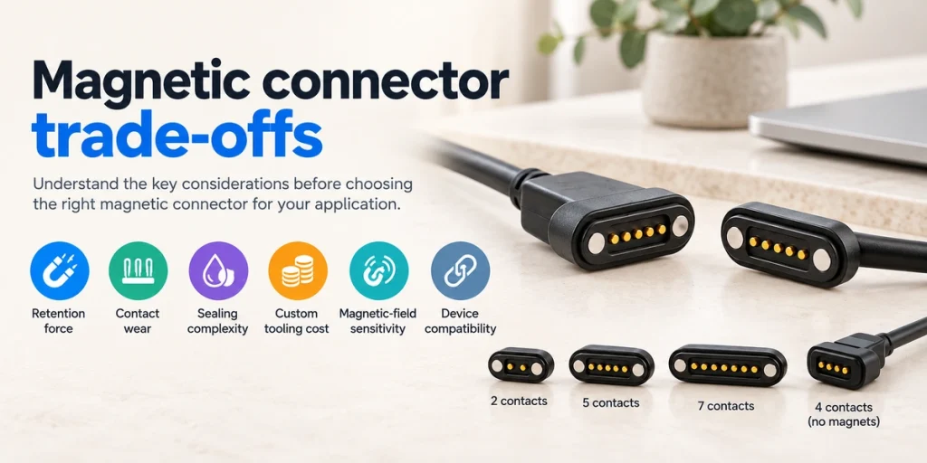
- Retention Under Real Loads
- Contamination and Contact Wear
- Sealing Complexity
- Customization Cost and Coordination
- Magnetic Fields and Interchangeability
- Matching the Application
- Comparison with Conventional Connectors
- Assessing System Reliability
- Engineering Questions
Magnetic guidance and detachable mating can simplify handling. Selection still needs to account for retention, contact wear, sealing, customization cost, magnetic-field effects and compatibility. Assess these six limitations against the actual device requirements.
Magnetic connectorsRetention Under Real Loads
Many magnetic interfaces retain the connection mainly through magnetic attraction. Where no additional latch is provided, retention behaves differently from a mechanically locked connector.
Seven factors influence the holding force:
Magnet dimensions and grade
Magnet quantity
Gap between mating surfaces
Housing geometry
Magnetic orientation
Mating alignment
External pull on the assembly
Cable tension, vibration, shock or an accidental pull can separate an interface whose magnetic retention is insufficient for those loads.
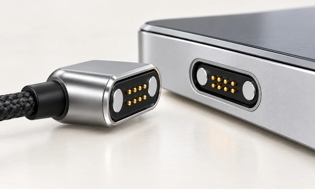
If the application requires a mechanical lock throughout severe continuous vibration or substantial tensile loading, evaluate a locking or otherwise restrained interface against that requirement.
In a different use case, deliberate breakaway can reduce cable strain during an accidental pull. The benefit depends on release force and the complete product geometry; it is not a guarantee against damage or falls.
Designing for the Required Retention
Possible design changes include selecting suitable magnetic force, increasing magnet size or quantity, and adding locating or keying features. Coordinate the magnetic circuit with the mechanical structure before choosing an approach.
Evaluate retention together with these six use conditions:
Cable weight
Applied pulling force
Vibration level
Mating orientation
Required release force
Operating environment
Industrial and robotic designs need evaluation under their actual mechanical conditions. Nominal magnetic force by itself does not establish suitability for the assembled device.
Contamination and Contact Wear
Many magnetic connectors use spring-loaded pogo contacts. Magnets guide the mate; the touching pins and pads carry power, data or other signals.
Electrical reliability therefore depends on the contact design as well as the magnetic system.
Dust, oil, sweat, moisture, oxidation and other contamination may build up at exposed contacts. Deposits or corrosion can raise resistance or produce intermittent contact over time, depending on the materials and exposure.
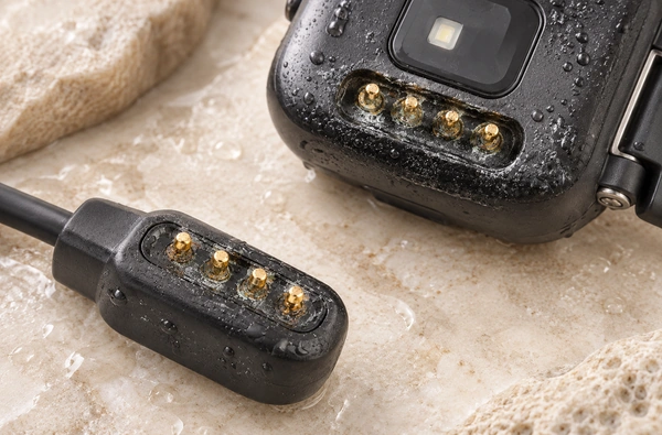
Repeated mating can change the mechanical and electrical behavior of spring contacts.
Review these seven contact-design inputs:
Contact material
Surface finish and plating
Spring force
Working stroke
Contact geometry
Required mating cycles
Environmental exposure
A wearable may meet sweat and skin contact. Industrial equipment may instead meet dust, oil or cleaning chemicals. Define those exposures separately when selecting contacts and protective measures.
Improving Contact Reliability
A suitable plating stack, controlled contact force, appropriate pogo-pin structure and protection from contamination can improve reliability. Verify the combination for the intended service rather than assuming one feature prevents all contact problems.
pogo pinFor an OEM design, assess the actual operating combination:
Voltage, current, contact resistance, mating cycles and environmental conditions must be considered together.
Contact count alone is insufficient for selection.
Sealing Complexity
Water protection needs to be addressed as part of magnetic-interface design.
An exposed interface may have openings around its pogo pins. Water, sweat, dust, salt spray and cleaning agents can call for additional protective measures. Their different exposures must be evaluated; a water-ingress rating does not establish resistance to every chemical or sweat condition.
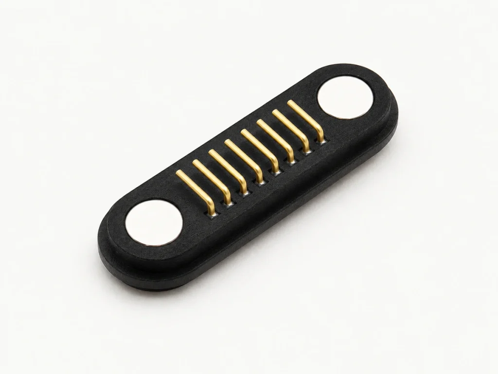
A sealed magnetic assembly may use the following measures:
waterproof magnetic connectorSealing rings
Adhesive seals
Protective housing geometry
Protected contact areas
Controlled mating surfaces
Defined assembly tolerances
The seal must protect the contact region while allowing magnetic positioning and the required pogo-pin movement.
The presence of a sealing ring alone does not demonstrate water protection.
Performance depends on the full structure, assembly process, housing interface and contact protection working together.
Defining Environmental Protection
Start by defining the protection required for the intended environment, then evaluate the assembled magnetic interface against it.
Include these eight exposure and use inputs:
Required IP rating and test conditions
IP ratingWater exposure
Dust exposure
Sweat exposure
Salt-spray exposure
Cleaning chemicals
Operating temperature
Mating frequency
For wearable, smart, outdoor and industrial devices, combine environmental requirements with the electrical and mechanical design. Protection requirements apply to the intended assembly and use conditions.
Customization Cost and Coordination
A magnetic pogo assembly may contain more parts than a simple electrical connector, depending on its construction.
Its possible components include:
Permanent magnets
Pogo contacts
Housing
Contact terminals
Cable
Sealing components
Custom mechanical parts
Component count and construction affect total cost alongside contact count.
Custom engineering and tooling may also influence development cost and lead time. Confirm those requirements for the proposed design rather than assuming a fixed schedule or fee.
A custom project may need changes to these ten features:
Contact count
Contact spacing
Housing size
Magnet arrangement
Cable length
Cable exit direction
90° cable head
180° cable head
Sealing structure
Required current rating
An existing standard design may be easier to source. A custom magnetic assembly can require closer engineering coordination to agree the interfaces and manufacturing details.
When Custom Design Is Useful
Consider customization when an available design cannot meet the product's mechanical or electrical requirements.
A compact wearable might need a small two-contact mate. A robotic design might need a higher-current path with separate power and signal contacts. These are different design requirements, not ratings established by the application name.
Balance these six requirements:
Size, current, contact configuration, magnetic force, environmental protection and manufacturing requirements.
Initial component price is only one part of that decision.
Magnetic Fields and Interchangeability
Assess the field generated by the connector magnets within the device.
Permanent magnets can be integrated into electronic products, but compatibility depends on the nearby components and layout. Give particular attention to magnetically sensitive devices rather than assuming that a small magnet is harmless in every design.
Examples of sensitive components include:
Magnetometers
Electronic compasses
Hall-effect sensors
Magnetic position sensors
Other magnetically sensitive components
Evaluate magnet strength, separation distance, orientation, shielding and the sensitivity of nearby components. Their combined behavior determines the effect in the device.
Place the connector with those field interactions in mind during mechanical design.
Confirming Interchangeability
Equal contact count does not establish compatibility between two magnetic mates.
For example, two five-contact designs can differ in:
5-pin magnetic connectorContact layout
Contact pitch
Housing dimensions
Magnet location
Magnet polarity
Mating-contact arrangement
Electrical specifications
The selection rule is:
Matching the number of contacts is only one part of compatibility assessment.
Before selecting a replacement or second source, confirm both mechanical dimensions and electrical requirements.
Keying and magnetic polarity can help prevent incorrect mating where they are designed into the assembly. Verify their behavior for the actual mate.
Matching the Application
These limitations identify what needs evaluation for a demanding product. A magnetic interface can still be considered where the device's mechanical, electrical and environmental requirements can be met and verified.
A magnetic interface may be useful for these nine requirements:
Quick physical attachment and removal
Blind mating with suitable guidance
Magnetic alignment
Compact conductive contacts
Detachable cables
Custom contact assignments
Frequent mating
Convenient charging access
Power and signals through one interface
Potential applications include wearables, smart glasses, hearing devices, smart mugs, portable electronics, industrial handheld equipment, robotics and other compact electronics. Each application still needs its own qualification.
Give additional attention to these seven demanding requirements:
High mechanical retention
Continuous severe vibration
Substantial environmental exposure
Very high current
Strict limits on magnetic fields
Standardized interoperability
Mechanical locking
Design Measures for the Limitations
Suitable component and structural choices can address several of these concerns. The following approaches require design and validation for the particular application.
| Design Requirement | Possible Design Approach |
|---|---|
| Greater retention | Evaluate magnet size, quantity and magnetic circuit |
| Accurate mating | Coordinate magnetic guidance with mechanical keying |
| Avoiding reverse polarity | Design polarity and error-resistant mating features |
| Stable conductive contact | Specify suitable pogo force and plating |
| Water protection | Evaluate rings, adhesive seals and protected contact geometry |
| Higher current | Size conductive contacts and layout for the complete current path |
| Power and signals | Allocate suitable separate power and signal contacts |
| Compact dimensions | Coordinate custom housing and contact arrangement |
| Cable exit direction | Select a 90° or 180° cable configuration |
Scroll horizontally to view every column.
A design may use larger power contacts and smaller signal contacts to suit different circuit loads. Contact sizing, resistance and thermal behavior must support the target device's requirements; mixed sizes alone do not establish a high-current rating.
high-current magnetic connectorComparison with Conventional Connectors
Compare magnetic and conventional interfaces using the product's mechanical, electrical, environmental and user-interface requirements.
| Factor | Magnetic Interface | Conventional Interface |
|---|---|---|
| Alignment | Magnetic guidance is possible | Manual or guided alignment, depending on design |
| Blind mating | Possible with suitable guidance | Depends on the connector design |
| Detachment | Can be easy when release force is suitable | May require deliberate insertion or latch release |
| Mechanical locking | Limited without an added lock | Available in many connector families |
| Customization | Custom arrangements are possible | Depends on the connector family |
| Water protection | Requires assembly-specific sealing design | Depends on construction and sealing |
| Pogo contacts | Used in many designs | May use other contact structures |
| Standardization | Many magnetic mates are manufacturer-specific | Some interfaces follow common standards |
| Power and signals | Can share an appropriately designed interface | Depends on the connector and pin assignment |
Scroll horizontally to view every column.
There is no single performance ranking that covers every magnetic and conventional connector.
Use the following product question to guide the comparison:
Which mechanical, electrical, environmental and user-interface requirements must this product meet?
Assessing System Reliability
Reliable mechanical and electrical performance is possible when the complete connector is specified and validated for its application.
Review these nine reliability inputs:
Magnetic holding force
Pogo-contact design
Contact plating
Mating-cycle requirement
Environmental conditions
Sealing structure
Mechanical alignment
Required current and voltage
Manufacturing tolerances
Assess the interface as a complete connector system. Its contacts, magnets, structure and installation interact during use.
Before finalizing an OEM design, provide contact count, current, voltage, dimensions, required cycles, IP requirements, cable direction and operating environment. These eight inputs give the manufacturer a basis for reviewing the proposed assembly.
Engineering Questions
What makes a magnetic connection reliable?
Reliability is possible when magnetic force, pogo structure, plating, environmental protection and mating requirements are matched to the application and validated together.
Which limitations need the most attention?
Consider retention relative to a locking connector, contamination and wear, sealing complexity, possible customization cost, magnetic fields and compatibility between designs. Their importance depends on the product requirements.
How does repeated mating affect durability?
Magnetic materials and spring contacts have different durability mechanisms. Repeated mating can change contact surfaces and spring behavior, so specify and verify the required cycles for the actual assembly.
Does magnetic mating establish waterproofing?
No. Some assemblies are designed for water protection, while others are exposed. Confirm the required IP rating using the complete sealing structure, installation and defined operating or test conditions.
Can a magnetic assembly support higher current?
It can, if contact size, resistance, thermal performance, conductor size and structure are engineered and validated for the required current. The magnetic mechanism itself does not set electrical capacity.
Are magnetic mates standardized?
Standardization and interchangeability vary. Contact count, dimensions, polarity, magnet arrangement, contact layout and electrical specifications can differ, so check the particular designs before combining them.
Selection Summary
Magnetic alignment, convenient mating, detachable connections and flexible pogo arrangements can be useful. Evaluate the limitations alongside these four benefits before integrating the interface.
The six review areas are retention, conductive-contact reliability, sealing, cost and customization, magnetic fields and application compatibility.
For OEM development, judge those areas against actual device requirements. Contact count and external size are only two of the inputs needed to select an assembly.
A magnetic pogo interface can be developed around electrical, mechanical, environmental and dimensional requirements. With suitable verification, the architecture may serve compact wearables, industrial equipment or robotic devices according to each application's needs.
magnetic pogo pin connector