
6-Pin Magnetic Charging Cables: An OEM Interface Design Guide
Published on September 29, 2026
- When Six Contacts Are Needed
- Assigning the Six Paths
- Voltage, Current and Conductor Requirements
- Cable Construction and Ends
- Designing the Magnetic Mate
- Reliability and Environmental Validation
- Information for Custom Development
A six-contact cable can combine power, data, ID, detection or control when the circuit requires them. Before prototyping, define assignments, current, cable ends, magnetic mating and reliability conditions for the complete OEM interface.
6 pin magnetic charging cableWhen Six Contacts Are Needed
List the functions crossing between cable and device. Basic charging may need power and ground; communication, identification, charger detection, control or other signals may need more paths according to the architecture.
One example assigns V+, GND, Data+, Data−, ID and Detect. Another uses two power contacts, two returns and two signals. Neither is a universal six-contact pinout or protocol. The Magtor 6-pin assignment guide discusses these circuit-specific choices further.
6 Pin Magnetic Connector Pinout
More contacts do not automatically increase charging speed or data rate. Six may suit six required paths, or an intentional allocation of multiple paths to power, return, communication and control.
Assigning the Six Paths
Define the pin map before mechanical approval. List every function, identify dedicated paths and decide whether power or ground needs multiple contacts.
| Pin | Example Configuration A | Example Configuration B |
|---|---|---|
| Pin 1 | V+ | V+ |
| Pin 2 | GND | V+ |
| Pin 3 | Data+ | GND |
| Pin 4 | Data− | GND |
| Pin 5 | ID | Signal 1 |
| Pin 6 | Detect | Signal 2 |
Scroll horizontally to view every column.
These assignments are examples. Similar-looking six-contact heads may have different wiring. Before prototyping, confirm electrical polarity, sequence, mating orientation and device PCB routing from the approved drawing.
A USB-A or USB-C source end is a separate interface from the six magnetic contacts. Apply the source connector's requirements and map the custom magnetic side to the OEM circuit's functions.
USB-CVoltage, Current and Conductor Requirements
Review current across the entire path: contact dimensions, resistance, working compression, conductor cross-section, cable length, PCB traces, mating condition and operating temperature. Contact count alone cannot establish capacity.
magnetic charging cablParallel power or return contacts need deliberate routing and validation of current sharing. Unused contacts do not automatically add capacity. Check voltage drop and temperature rise at the actual load, especially with a long cable, small pins or continuous charging.
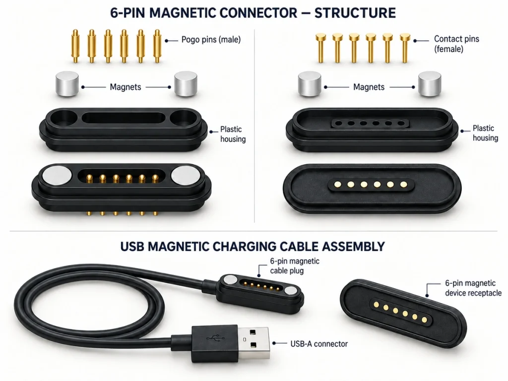
Follow the complete electrical path:
Power supply → source connector → cable conductor → magnetic contact → device-side pad → PCB → load.
Each segment affects resistance and thermal behavior. For sample review, provide voltage, normal current, any peak current, cable length and duty cycle.
Cable Construction and Ends
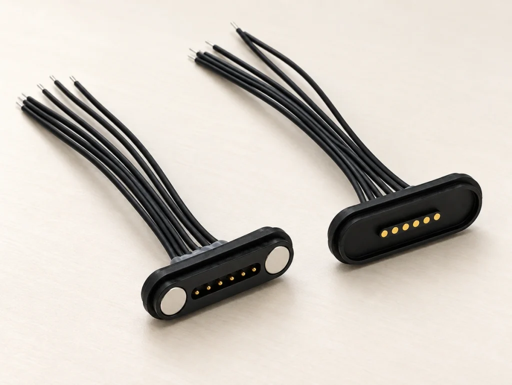
The assembly includes both the magnetic head and an end suited to the power source, fixture, internal harness or host. Options include USB-A, USB-C, bare wires, terminals and custom connectors.
| Cable End | Possible Use |
|---|---|
| USB-A | Chargers, adapters or supported legacy hosts |
| USB-C | Supported modern power sources or hosts |
| Bare wire | Prototype wiring or direct PCB integration |
| Wire terminal | Internal harnesses or equipment assemblies |
| Custom connector | Device-specific power or communication systems |
Scroll horizontally to view every column.
Specify length, jacket material, conductor gauge, shielding and exit direction. A 180° outlet may suit routing away from the mating surface; a 90° exit can reduce protrusion at a side or bottom installation.
Coordinate cable decisions with the mechanical layout. Bending space, the enclosure opening and strain-relief area affect the housing and finished assembly.
Designing the Magnetic Mate
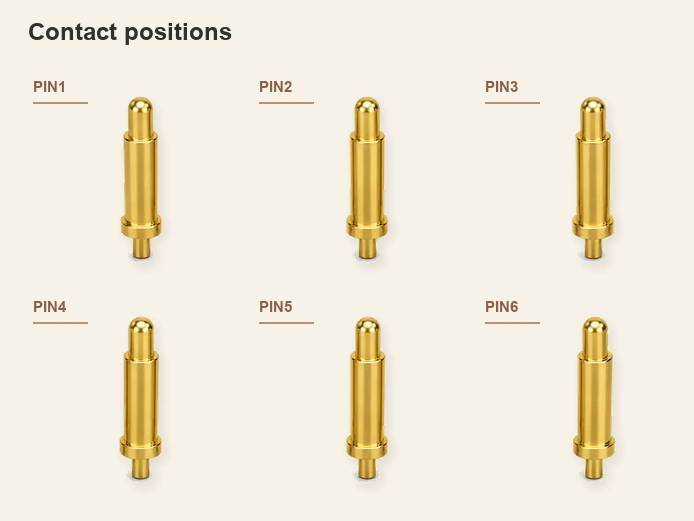
Design for repeatable contact position and protection against wrong polarity or misalignment. Define pitch, working stroke, mating height, magnet position and polarity, housing geometry, exit direction and device-side location.
Insufficient holding force may let normal movement interrupt charging; excessive force can transfer unwanted pulling loads during release. For wearables, smart devices or controlled-breakaway applications, select force for expected use rather than maximizing it.
Housing contours, locating features, recesses and asymmetric structures can guide orientation before the contacts touch. Validate those keying features for the intended mate.
Reliability and Environmental Validation
Set requirements for actual exposure: sweat and daily charging in wearables, repeated mating and cleaning in medical or handheld equipment, dust and vibration in industrial docks, or moisture outdoors.
Possible evaluations include mating cycles, resistance, force, stroke, cable pull or flex, plating thickness, salt spray, temperature rise and sealing. Select gold surfaces, nickel barriers or other finishes for the required contact life and corrosion exposure, with defined methods and acceptance criteria.
salt-spray testingGold platingWater protection belongs to the complete connector and enclosure. For an IP requirement, assess device housing, mating interface, seals, PCB installation and manufacturing process together.
IP-rated productInformation for Custom Development
Provide electrical and mechanical requirements before requesting the final structure so the development review can address the actual application.
| Requirement | Information Needed |
|---|---|
| Contact count | 6 pins |
| Pin assignments | Required V+, GND, Data, ID, Detect, Control or other paths |
| Operating voltage | Device's specified voltage |
| Operating current | Normal and peak load |
| Cable length | Required finished length |
| Wire specification | Known gauge or required load |
| Cable end | USB-A / USB-C / bare wire / terminal / custom |
| Exit direction | 90° / 180° |
| Installation space | 2D drawing or available dimensions |
| Mating direction | Required orientation |
| Magnetic holding force | Target force or use condition |
| Operating environment | Indoor / wearable / medical / industrial / outdoor |
| Sealing | Required rating or sealing boundary |
| Mechanical life | Required mating cycles |
| Prototype quantity | Initial sample quantity |
Scroll horizontally to view every column.
PCB layouts, enclosure drawings and existing dimensions reduce uncertainty. When fitting an existing product, confirm pitch, width, height and housing opening in particular.
From Requirements to Assembly Validation
Select by functions, current, space, cable end, mating structure and environment. Early definition can reduce wiring mistakes, mechanical conflicts, voltage-drop issues and unnecessary prototype revisions.
For OEM development, supply the pin map, current and voltage, length, end type, device drawing, sealing needs and mating-life requirement. Use them to develop the head and cable together and progress from the drawing to sample validation.