
Magnetic Cables: How the Contact System Works and Where It Fits
Published on September 23, 2026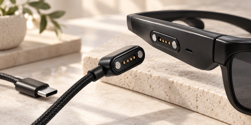
- Magnetic-Cable Connection Sequence
- Cable Types and Configurations
- Power and Data Functions
- Conductive Cables and Inductive Charging
- Applications for Magnetic Cables
- Defining an OEM Cable Interface
A magnetic cable is a wired interface whose magnets help position and retain two mating parts. Conductive contacts, such as pogo pins or pads, establish the paths for power, data or control once the surfaces touch.
Applications include charging, docking, power delivery and signals in wearables, smart glasses, medical electronics, docks and other compact products. Designs may use 2, 3, 4, 5, 6, 8 or more contacts with USB, bare-wire, terminal or custom OEM ends, according to the required circuit.
Magnetic-Cable Connection Sequence
The cable-side head mates with a device-side contact interface. As it approaches, magnetic attraction helps position the halves. Pogo pins or other contacts then touch the corresponding pads and complete the circuit's electrical paths.
A typical physical path is:
Power source or host → cable → magnetic connector → pogo pins / contacts → device contact pads → PCB → device electronics.
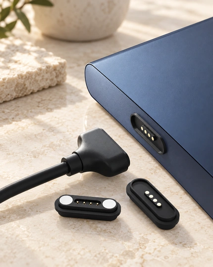
In this arrangement, magnetic force assists alignment and retention while conductive contacts carry the electrical paths. Keep the mechanical capture function separate from power and data transmission when developing the interface.
Cable Types and Configurations
Classify the design by contact count, cable end, connector geometry and electrical functions. A two-contact charging cable may use power and ground. Three-, four-, five-, six- or eight-contact versions can allocate more paths to ID, detection, control or data as the device needs.
2 pin magnetic charging cableOEM options include USB-A or USB-C ends, bare wires for PCB integration and terminals for internal harnesses, with 90° or 180° exits for different enclosures. Magtor provides 3-, 4-, 5-, 6- and 8-pin cable configurations for different device architectures.
3 pin magnetic charging cables4 pin magnetic charging cables5 pin magnetic charging cables6 pin magnetic charging cables8 pin magnetic cable connectors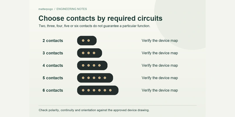
Contact count is not a wiring standard. Two five-contact cables may have entirely different assignments. Define each path from the schematic, voltage, current, communication requirements and approved pin map.
Power and Data Functions
A cable can carry both functions when its pin assignment, internal conductors, contacts, PCB and communication interface are designed for them. Some configurations charge only; others allocate paths to power, ground, data, ID, detection and control.
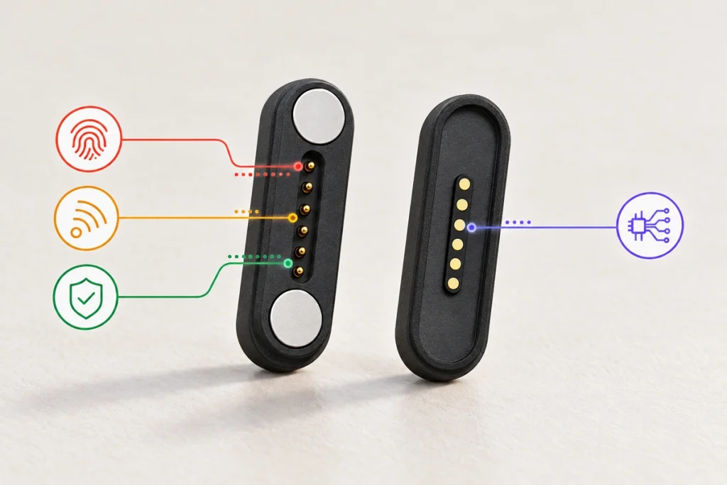
One four-contact example might use VBUS, GND, D+ and D−, while another uses different signals. Count alone cannot establish USB or another protocol. The guide to magnetic-connector data transfer explains the complete-channel requirements further.
Can Magnetic Connectors Transfer Data?A USB-C end does not automatically provide every USB rate or Power Delivery mode. Actual functions depend on the full electrical implementation. USB-IF maintains the USB Type-C cable and connector specification, including its Release 2.5 document entry.
USB Implementers Forum (USB-IF)Conductive Cables and Inductive Charging
Magnetic and conventional USB cables both use conductive power paths. Their device-side mating differs: an inserted plug uses its mechanical receptacle, while a magnetic head adds attraction for positioning and retention.
Qi uses a transmitter coil and a receiver coil. Alternating transmitter current creates a changing magnetic field that induces voltage in the receiver, transferring energy across a gap without exposed conductive charging contacts. WPC describes this as magnetic induction; the system also uses communication to control charging.
Wireless Power Consortium explanation of Qi charging| Comparison Feature | Magnetic Cable | Standard USB Cable | Inductive Wireless Charging |
|---|---|---|---|
| Power path | Conductive mating contacts | Conductive mating contacts | Magnetic induction |
| Device connection | Magnet-assisted mating | Mechanical insertion | No conductive charging-contact mate |
| Alignment | Magnetic capture with mechanical positioning | Manual insertion into the receptacle | Transmitter and receiver coil alignment |
| Wired data | Possible with a suitable electrical design | Possible with the supported USB design | Distinct from wired USB data; charging-control communication exists |
| Contact-layout customization | Can be configured for the project | Physical layout follows the connector standard | Does not use pogo-pin contact allocation |
| Typical OEM function | Charging, docking, power and signals | Charging and supported communication | Contactless power transfer |
Scroll horizontally to view every column.
A magnetic pogo-pin cable remains a wired interconnect. Its magnets help the parts mate; energy passes through the conductive contacts rather than across an inductive gap.
Applications for Magnetic Cables
Consider a magnetic cable for compact detachable interfaces or frequent mating. Wearables and smart glasses may have limited receptacle space, so a small surface-contact interface can avoid repeated plug insertion.
Other possible uses include medical electronics, beauty products, docks, handheld terminals, smart-home products, portable electronics and custom modules. A charging-only wearable may use two contacts, whereas docking data, ID or detection can call for additional paths.

For sweat, moisture, dust or frequent handling, review plating, corrosion protection, sealing, mating cycles, contact force and enclosure design as a system.
Defining an OEM Cable Interface
Define voltage, maximum current, power and return paths, data or signals, ID or detection and the pin assignments first. Then specify contact count, pitch, dimensions, electrical polarity, magnetic polarity, working stroke and the device-side counterpart. The Magtor contact-count selection guide expands this review.
how to choose the right magnetic charging cable pin countReview cable length, wire gauge, diameter, USB-A or USB-C ends, bare-wire or terminal ends, 90° or 180° exits, magnetic force and mounting space. Include sealing, life cycles, vibration, sweat and the intended environment. Magtor magnetic cable connector configurations are assessed against these device-specific requirements.
Magnetic Cable Connector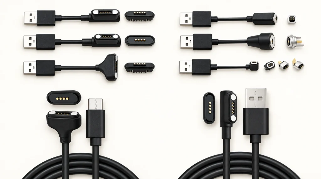
Before prototyping, provide the schematic, voltage and current, pin definitions, housing dimensions, PCB position, cable end and environment. Define the cable and device-side counterpart together as one connection system.