
Pogo Pin Charging or USB-C: Which Interface Fits Your Device?
Published on September 22, 2026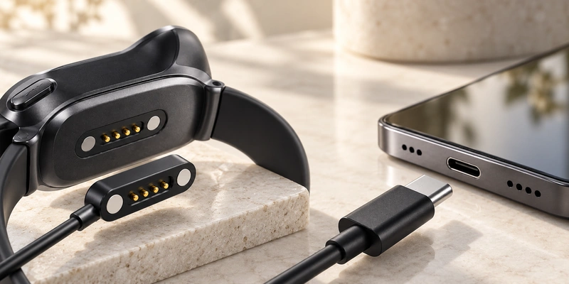
- How Pogo Pin Charging and USB-C Connect
- Comparing the Two Interfaces
- Fitting the Interface into a Compact Device
- Specifying Power and Data Functions
- Water Exposure and Wearable Design
- Limitations of Each Interface
- Choosing an OEM Charging Architecture
Both pogo pin charging and USB-C establish a conductive electrical connection. Their integration differs: pogo contacts can follow a custom geometry, fit compact products and optionally use magnets for alignment; USB-C provides a standardized interface and a broad ecosystem for power, data and accessories. Product size, charging power, data functions, water protection, environmental exposure and everyday charging use all influence the choice.
How Pogo Pin Charging and USB-C Connect
A pogo pin charging interface forms its electrical connection when spring-loaded contacts compress onto mating pads. Contact count, pitch, working height, spring force, pad position and housing geometry can be configured for the device. Adding magnets can guide alignment and hold the parts together. The resulting magnetic charging connector can provide a compact interface for wearables, charging docks, smart glasses, handheld equipment and other custom products.
magnetic charging connector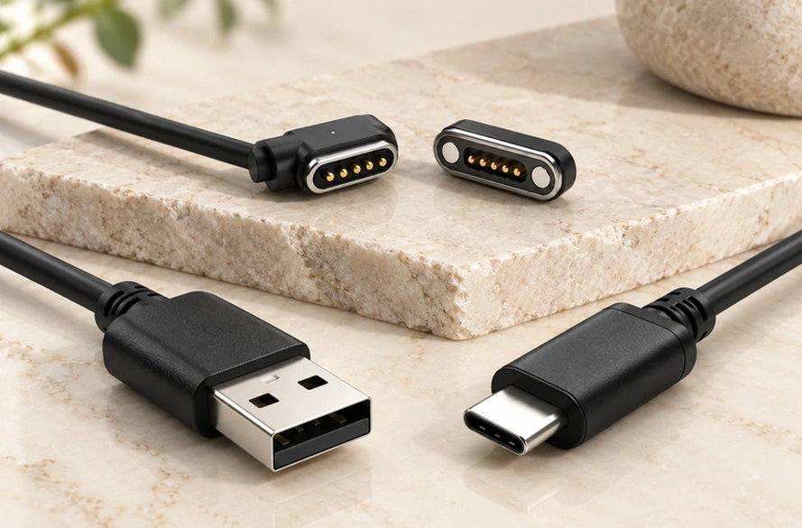
USB-C pairs a standardized plug with a receptacle and specifies their mechanical and electrical requirements. USB-IF developed this connector for smaller, thinner platforms while retaining functions within the wider USB ecosystem. The USB Type-C Cable and Connector Specification describes that system. Its standardized compatibility is a different design priority from the freedom to configure a custom pogo contact interface.
USB Type-C Cable and Connector SpecificationComparing the Two Interfaces
| Factor | Pogo Pin Charging | USB-C |
|---|---|---|
| Contact method | Spring-loaded direct contact | Plug and receptacle |
| Interface geometry | Highly customizable | Standardized |
| Alignment | Mechanical and/or magnetic | Manual insertion |
| Device-side depth | Can be very low-profile | Requires receptacle space |
| Pin configuration | Application-specific | Defined USB-C connector |
| Power capability | Depends on contact design | Strong standardized power ecosystem |
| Data capability | Possible with suitable design | Major advantage |
| Breakaway connection | Possible with magnets | Generally not |
| Exposed contacts | Usually yes | Contacts inside receptacle |
| Docking applications | Very suitable | Requires plug insertion |
| Accessory compatibility | Usually device-specific | Broad |
| Environmental design | Customizable | Requires port/enclosure integration |
Scroll horizontally to view every column.
The preferred interface depends on the product. Pogo pin charging allows the contact layout to be adapted to the device, whereas USB-C gives users access to an established cable, charger and data ecosystem with less reliance on proprietary accessories. A Magnetic Cable Connector can suit a custom dock; USB-C can be preferable when standardized interoperability is central to the design.
Magnetic Cable ConnectorFitting the Interface into a Compact Device
Pogo contacts need not follow a fixed receptacle outline, giving engineers room to adapt pin count, pitch, working height, magnet position, contact-pad layout, cable outlet direction and housing geometry. A simple charging circuit may use two contacts; additional contacts can serve detection, ID, signal or control functions. As the Magnetic Charging Cable Pin Count Guide explains, the required electrical architecture should determine the contact count.
Magnetic Charging Cable Pin Count Guide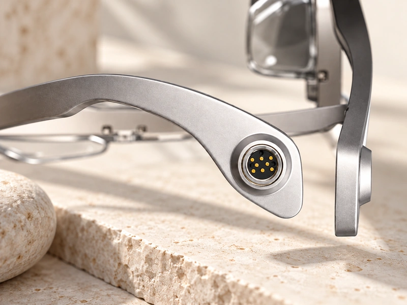
USB-C was developed for thin, light products and should not be dismissed as inherently oversized. Its receptacle nevertheless requires a defined volume, PCB integration and an enclosure opening. A custom external mating surface can distribute pogo contacts where space allows, including on very thin smart glasses and compact wearables. Some smart-glasses charging architectures place pogo contacts on the small device and USB-C on the larger case or dock, using the available space at each stage.
smart-glasses charging architecturesSpecifying Power and Data Functions
For a standardized interface with broad power and data support, USB-C provides an established ecosystem. USB Power Delivery can support up to 240 W where the source, cable, connector and device meet the appropriate specification. A USB-C connector does not, by itself, guarantee USB PD, USB4 or a particular data rate; the implemented system determines the available functions. The USB-IF USB Power Delivery information covers the power-delivery framework.
USB-IF USB Power Delivery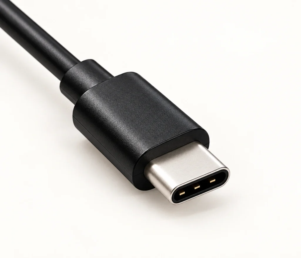
Pogo pin performance must be specified for the application. Pin diameter, contact resistance, the number of power contacts, spring force, plating, cable wire gauge, thermal conditions and connector structure all affect current capacity. Multiple contacts may carry power, signals, ID, control or data, but their count does not define a communication protocol. The Magtor guide on whether magnetic connectors can transfer data examines pin assignment, cable construction, PCB design and signal requirements. A 6 Pin Magnetic Charging Cable can supply several independent electrical paths for a more complex design without establishing a universal pinout.
magnetic connectors can transfer data6 Pin Magnetic Charging CableWater Exposure and Wearable Design
External contact pads can reduce the device-side depth needed for a charging interface, making pogo pin charging useful where a deep receptacle is difficult to fit. Examples include smartwatches, fitness devices, smart glasses, medical wearables and other compact electronics. Pogo pins alone do not make the product IP67 or IP68. The complete enclosure, seals, adhesives, contact inserts, assembly process and validation determine its final ingress protection. IEC 60529 defines the IP classifications.
IEC 60529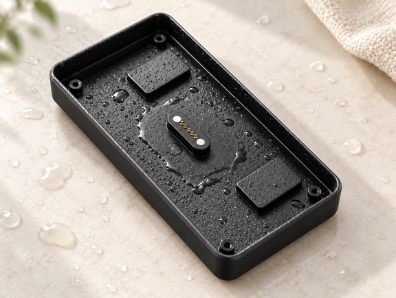
In a wearable, exposed pins and pads may encounter sweat, moisture, skin oils, cosmetics and cleaning agents. Evaluate plating thickness, nickel barriers, contact force, mating-pad finish and corrosion resistance together. The Magtor Pogo Pin Gold Plating guide considers working stroke, spring force, wear and environmental exposure when discussing plating life. The guide to preventing charging-contact corrosion in wearables provides further discussion of sweat and multi-layer plating.
Pogo Pin Gold Plating guidepreventing charging-contact corrosion in wearablesLimitations of Each Interface
Pogo pin charging generally uses a proprietary interface. Connector dimensions, contact positions, polarity, magnet orientation, pin assignments and cable construction must match, so a lost charger usually cannot be replaced with an arbitrary generic cable. Exposed contacts may also suffer contamination, mechanical wear or corrosion. Reliable contact requires suitable alignment, working stroke, spring force, plating and pad design. These choices are particularly relevant to high-cycle products, where repeated mating gradually changes the contact surfaces.
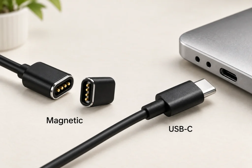
USB-C gives users broad accessory compatibility, while requiring a receptacle that takes enclosure and PCB space and undergoes repeated plug insertion. Dust or debris may enter the port, and water-resistant products need appropriate sealing around it. Its standardized mechanical architecture can reduce proprietary accessory requirements. Pogo contacts instead allow greater freedom in the charging geometry, with a more device-specific accessory ecosystem.
Choosing an OEM Charging Architecture
A pogo pin interface may suit a product that prioritizes compact custom geometry, frequent docking, magnetic alignment, breakaway behavior or tailored power and signal contacts. Establish the electrical requirements before selecting pin count, current rating, working stroke, spring force, plating, magnetic force, mating-pad design, cable structure and environmental protection. The Magtor Magnetic Cable Connector selection guide describes how to review these parameters together.
Magnetic Cable Connector selection guideConsider USB-C when widely compatible cables, standardized charging accessories, standardized high-power capability or mainstream wired data functions are priorities. The two interfaces can also serve different parts of the same product: pogo contacts connect a compact device to its dock or case, and USB-C connects that dock or case to the external supply. This arrangement uses each interface where its mechanical and electrical characteristics suit the design.
Matching the Interface to the Product
Pogo pin charging and USB-C both make conductive connections, with different integration priorities. Pogo contacts offer a configurable geometry, compact mounting, magnetic docking and flexible contact assignments. USB-C supplies a standardized ecosystem for power, data and accessories. OEM selection should consider device size, required power and data, enclosure design, environmental exposure, mating frequency and user expectations. For some compact products, pogo contacts at the device and USB-C at the charging dock or case can combine the benefits of both approaches.