
How Watches Charge: Inductive and Magnetic Contact Systems
Published on September 8, 2026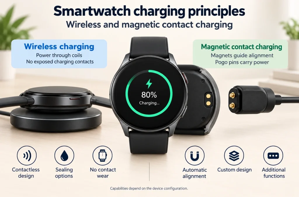
- Two Common Charging Paths
- Inductive Charging in a Watch
- Magnetic Contact Charging
- Comparing the Power Interfaces
- Why Consider Magnetic Pogo Contacts
- Limits of an Exposed Interface
- Matching the Method to the Watch
- Specifying the Charging System
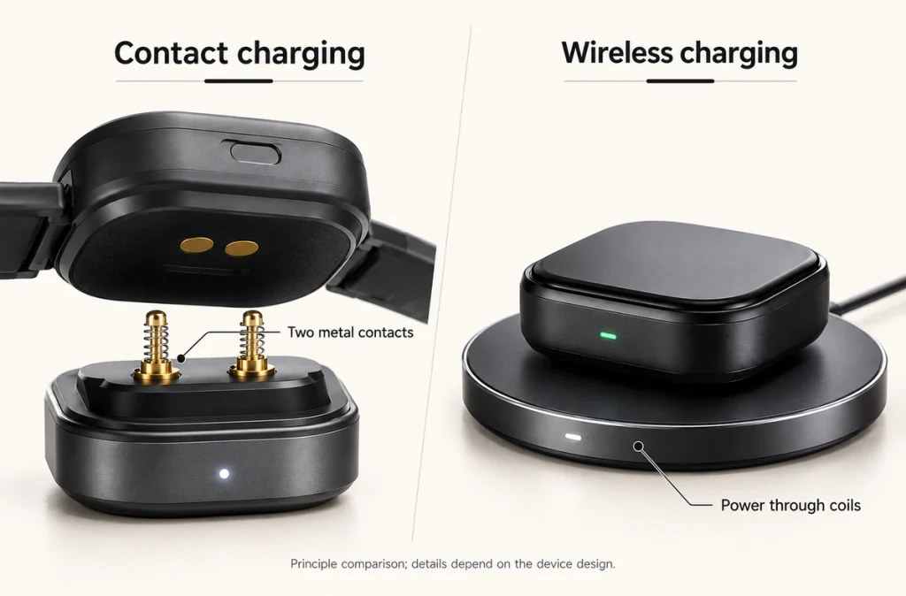
Watches can charge through inductive coupling or a magnetic contact interface. The first transfers energy between coils without exposed conductive contacts; the second uses magnets for positioning and pogo pins or pads for direct conduction.
Two Common Charging Paths
Two commonly used arrangements are:
Inductive path: power source → driven transmitter coil → magnetic field → receiver coil → rectification and charging management → battery.
Contact path: power source → cable → magnetic head → pogo pins → device pads → charging management → battery.
reference smartwatch instructions describe magnetic alignment with a charging puck. A reference smartwatch model’s accessory description identifies a magnetic pin charger with a USB-C source end. These are product-specific examples, not a statement that all watch generations share one interface.
Technical documentation to requestTechnical documentation to requestMagnetic positioning alone does not identify wireless power transfer.
Inductive Charging in a Watch
A driven transmitter coil creates an alternating magnetic field. The watch's receiver coil couples energy from that field, and its rectification and charging electronics deliver controlled power to the battery.
The Wireless Power Consortium's How Qi Works explanation describes this two-coil principle and the associated system control. It does not imply that every smartwatch implements Qi.
Wireless Power Consortium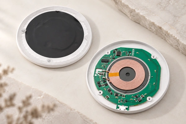
Potential design benefits include:
No exposed conductive charging contacts
No wear of pogo contacts at the power interface
Integration with a sealed external surface
Coil spacing and alignment affect transfer efficiency, along with circuit losses and thermal design. Magnets can help position the watch, but the complete system determines performance.
Magnetic Contact Charging
This architecture supplies power through a physical conductive connection.
Magnets guide and retain the head. Spring pins, compressed within their working range against the matching pads, provide contact pressure and carry current.
For charging alone, one possible assignment is:
Pin 1 → V+. Pin 2 → GND.
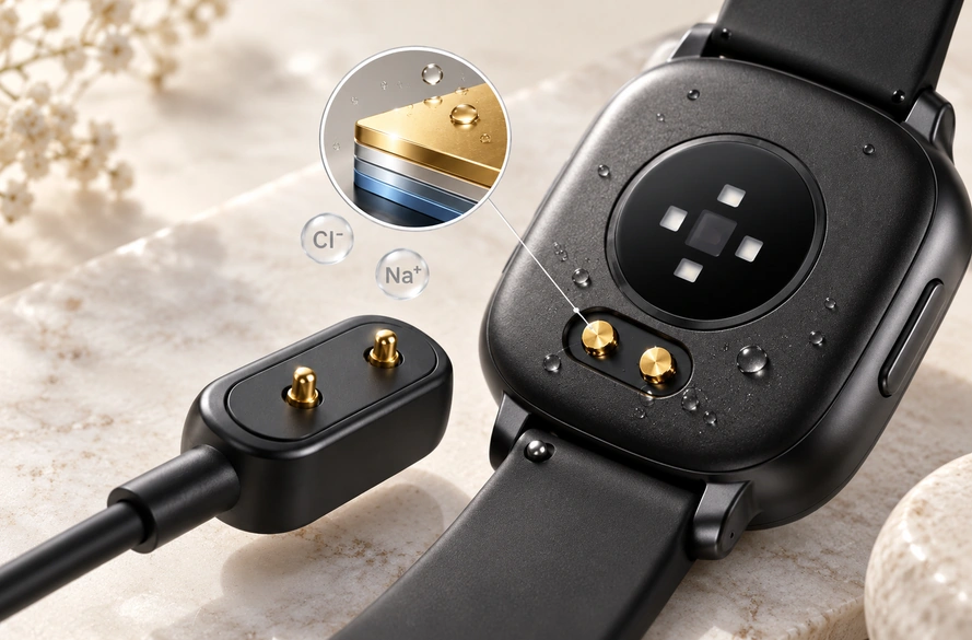
A 2 Pin Magnetic Charging Cable can suit a compact power-and-ground interface when its pinout and ratings match the device.
2 Pin Magnetic Charging CableThe guide How Do Magnetic Charging Connectors Work? provides further detail on this arrangement.
How Do Magnetic Charging Connectors Work?Comparing the Power Interfaces
Classify the interface by how power crosses it, rather than by whether magnets are present.
| Feature | Inductive wireless charging | Magnetic contact charging |
|---|---|---|
| Power transfer | Electromagnetic induction | Direct conductive contact |
| Pogo pins | Not needed for power transfer | Often used |
| Exposed contacts | Not required | Usually present |
| Magnetic alignment | Possible | Common |
| Contact wear | No conductive mating wear | Possible |
| Additional application signal pins | Usually need a separate interface | Possible with assigned paths |
| Custom conductive contact count | Not applicable to the coil power interface | Configurable for the device |
Scroll horizontally to view every column.
In summary:
Magnetic inductive charging: magnets position, coils transfer energy. Magnetic contact charging: magnets position, physical contacts conduct power.
See Choosing Between Contact and Wireless Charging for the broader comparison.
Contact Charging vs Wireless ChargingWhy Consider Magnetic Pogo Contacts
A matched magnetic pogo design can offer a compact watch-side interface and guided docking without a conventional plug being inserted.
Configurable design features include:
Contact count
Pin pitch
Magnetic retention force
Electrical polarity and magnet orientation
Pogo working stroke
Cable outlet direction
Housing geometry
Additional paths can be assigned to data, identification or control when the wiring and electronics support them.
The two-contact smartwatch cable guide covers wearable-specific integration requirements.
2 Pin Magnetic Charging Cable for SmartwatchesLimits of an Exposed Interface
The conductive contacts are usually exposed, which adds environmental design requirements.
Sweat, moisture, dust, skin oils and repeated wear can raise resistance or contribute to corrosion over time.
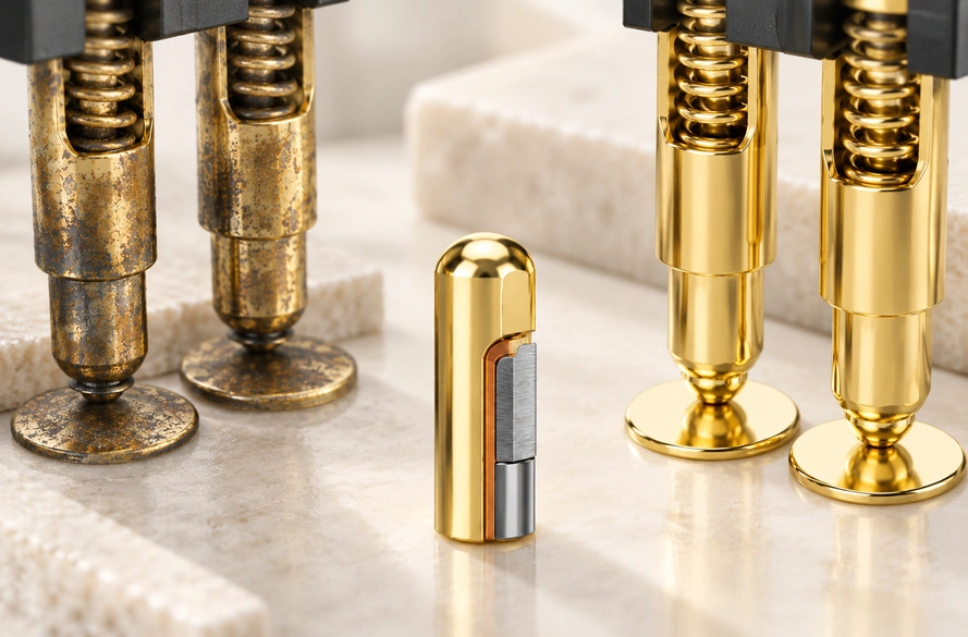
Specify plating, contact force and working stroke, and validate the assembly for its environment.
Reducing Corrosion Risk at Wearable Charging Contacts discusses the exposure and validation measures in more detail.
How to Prevent Charging Contact Corrosion in Wearable DevicesMatching the Method to the Watch
There is no universally preferable architecture.
Consider induction when the design needs:
A contactless external appearance
No exposed conductive charging surfaces
A sealed outer surface
Consider conductive magnetic docking when the design needs:
A compact conductive interface
Guided alignment
Additional signal contacts
An interface tailored to the device
Weigh available space, charging demands, water protection, heating, contact life and data functions together.
Specifying the Charging System
Begin with the watch's requirements and charging electronics.
For charging only, two contacts assigned to V+ and GND may be sufficient.
For data, identification or control as well, assess a multi-contact Magnetic Cable Connector with the required circuit and cable paths.
Magnetic Cable ConnectorConfirm:
Available device space
Charging current
Power alone or power plus data
Sweat and water exposure
Expected mating cycles
Magnetic alignment
The required cable termination
The Magnetic Cable Connector Selection Guide provides additional selection guidance.
How to Choose a Magnetic Cable Connector for Your DeviceSelecting the Complete Charging Path
Inductive and magnetic conductive systems are two common watch-charging arrangements; the particular product determines which is used.
Coils transfer energy in an inductive system, while pogo pins and pads form the conductive path in contact charging. Magnets guide the parts, and charging electronics regulate power to the battery.
A compact two-contact interface can serve power and ground when charging alone is needed. A multi-contact design can add data or control paths when the full electrical implementation supports them.
Choose according to watch size, exposure, charging requirements and electrical architecture.