
What Are Small Charging Contacts Called?
Published on September 4, 2026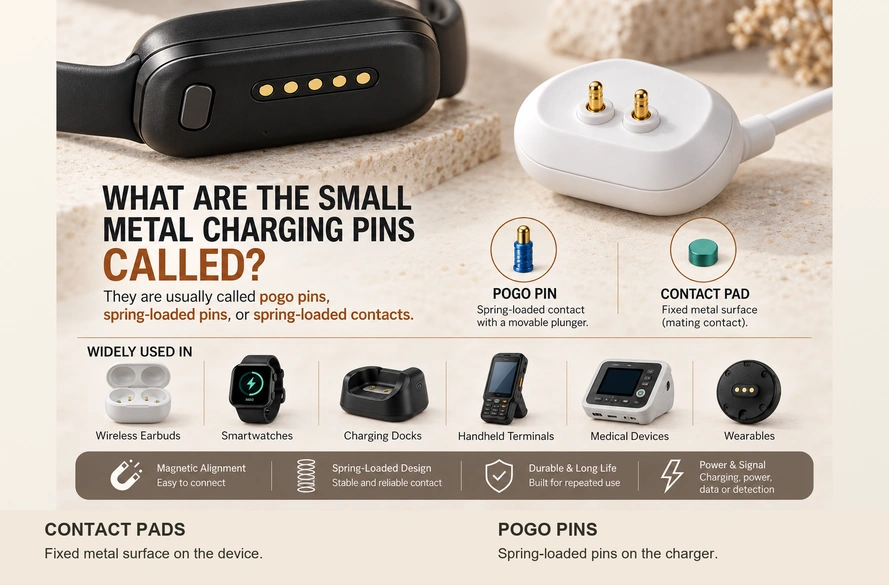
- Names for Small Charging Contacts
- The Pogo Pin Structure and Docking Process
- Distinguishing Pins from Pads
- Typical Charging Applications
- The Role of Magnets
- Engineering Selection Criteria
A small charging contact with a spring-driven movable plunger is commonly called a pogo pin, spring-loaded pin or spring-loaded contact. The fixed conductive surface it mates with is a contact pad or charging contact.
Gold color alone does not identify a pogo pin. The moving spring contact is generally the pin; its flat, fixed counterpart may be called a contact pad, mating contact or charging contact.
Examples occur in wireless earbuds, smartwatches, charging docks, wearables, handheld terminals, medical devices and other compact rechargeable products.
wireless earbudscharging docksNames for Small Charging Contacts
Two, three or several small gold-colored pins may be described as pogo pins when they have the spring-loaded moving structure.
Other descriptions include:
Spring-loaded contacts
Spring-loaded pins
Charging pins
Battery contacts
Charging contacts
Use the component's construction to decide which term is accurate.
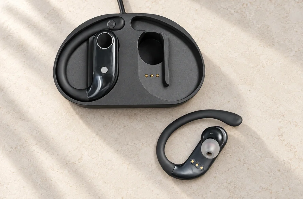
A pogo pin has a plunger that moves inward under pressure from its mating surface, rather than being a fixed metal piece.
Spring-loaded contacts can maintain a connection despite small variations in the relative positions of mating parts, within their design limits. Charging cradles for handheld devices are one common application.
A simple identification check, with power disconnected and only where the manufacturer permits it, is:
A contact that moves inward under suitable gentle pressure is likely a pogo pin or another spring-loaded contact.
A fixed, flat conductive surface is more likely a mating pad.
This structural distinction helps with both interface design and fault diagnosis.
The Pogo Pin Structure and Docking Process
The pin combines a conductive contact with spring-generated pressure to establish electrical contact.
Three parts make up a typical pin:
Plunger, spring and barrel.
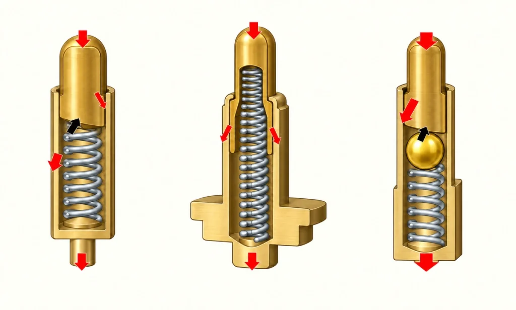
The plunger moves and touches the mating surface.
The spring pushes the plunger outward and supplies pressure within the intended working range.
The barrel guides that motion and contains the spring.
In a typical dock, seating the device brings its mating surface against the plunger.
The sequence is:
The device moves toward the contacts.
↓
The pin meets the mating pad.
↓
The plunger moves into its working stroke.
↓
The spring maintains contact pressure.
↓
The conductive connection is made.
Compared with a rigid contact, spring motion can accommodate small height and position differences within the available stroke and alignment tolerances.
That compliance can be useful where products connect and disconnect repeatedly.
A dock may not locate a handheld terminal with perfect precision. Housing, PCB, cradle and contact surfaces each contribute dimensional tolerances.
The specified working stroke can take up some of that variation while keeping the contacts engaged.
Available spring contacts differ in operating force, working height, current rating, plating and mating life. Select those specifications for the device rather than choosing by appearance.
Distinguishing Pins from Pads
A pogo pin and its mating pad belong to the same interface, but they have different structures and roles.
The Spring-Loaded Pin
The pogo pin is usually the spring-loaded member.
Its usual components are:
A movable plunger, a spring and a barrel.
Compression moves the plunger and produces contact pressure within the specified stroke.
The Mating Pad
A pad is typically a fixed conductive surface.
Possible forms include:
A round gold-colored pad, a rectangular metal area, a PCB contact or a recessed charging contact.
The pad in this arrangement has no spring-loaded motion.
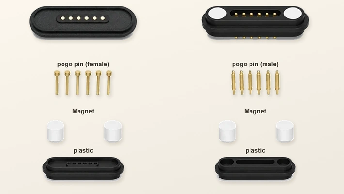
Magtor distinguishes spring contacts from their mating surfaces. Pad materials and finishes can be specified for durability and corrosion resistance, with performance dependent on the complete contact pair and operating conditions.
MagtorThis distinction accounts for a common observation on rechargeable devices.
For example, one arrangement has:
Charger: two movable gold-colored pins. Device: two fixed, flat gold-colored circles.
In that example, the movable contacts are the pogo pins.
The fixed circles are their mating pads.
The phrase 'gold dots on a smartwatch' therefore does not identify the spring-loaded component by itself.
A useful first distinction is:
Movable contact: likely a pogo pin. Fixed flat surface: likely a mating pad.
Reliable operation requires both mating surfaces to work together.
Typical Charging Applications
Spring contacts can suit compact products that need repeated electrical connection without a conventional plug being inserted on every use.
Earbud Charging Cases
Many earbud cases have pogo pins that mate with metal pads on the earbuds.
With the earbuds seated in their cavities, the case supplies charging power through those contacts and the charging electronics.
The user docks the earbuds in the case instead of attaching a separate cable to each one.

Watches and Other Wearables
Smartwatches provide another familiar application.
Some watch cables pair spring contacts with magnets.
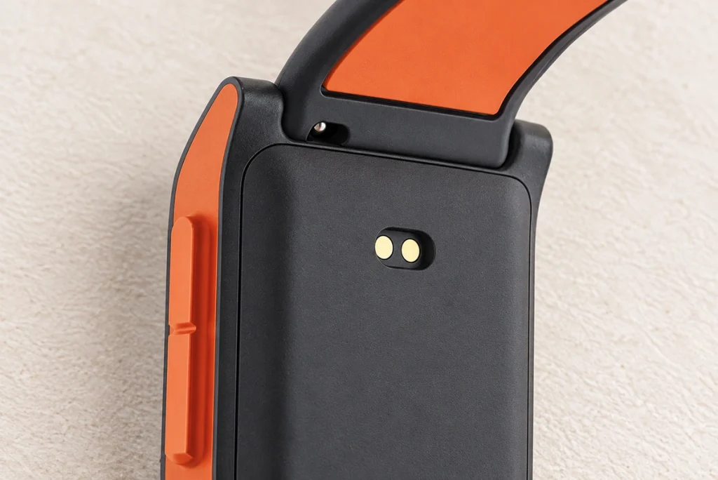
For a specific example, the Reebok Stride charging instructions describe aligning the charger's magnetic POGO pins with the metal contacts on the watch back. This is that product's docking procedure, rather than a universal watch pinout.
The example separates the two members clearly:
Spring pins on the charger and fixed contact pads on the watch.
Charging Cradles
Handheld terminals, barcode scanners, radios, POS devices and industrial electronics may use a charging cradle.
DigiKey's spring-contact guide lists cradles for barcode scanners and mobile radios as application examples.
The user seats the equipment in the cradle.
The cradle geometry positions it while the spring contacts establish the conductive connection.
Compact Medical and Wearable Electronics
Medical electronics and wearables can use this approach where a conventional connector would consume scarce housing space or require frequent manual insertion.
Depending on the circuit, contacts can be assigned to:
Power, ground, detection, identification or other project-specific functions.
Contact count does not define their functions. Specify the pinout from the device's electrical architecture.
The Role of Magnets
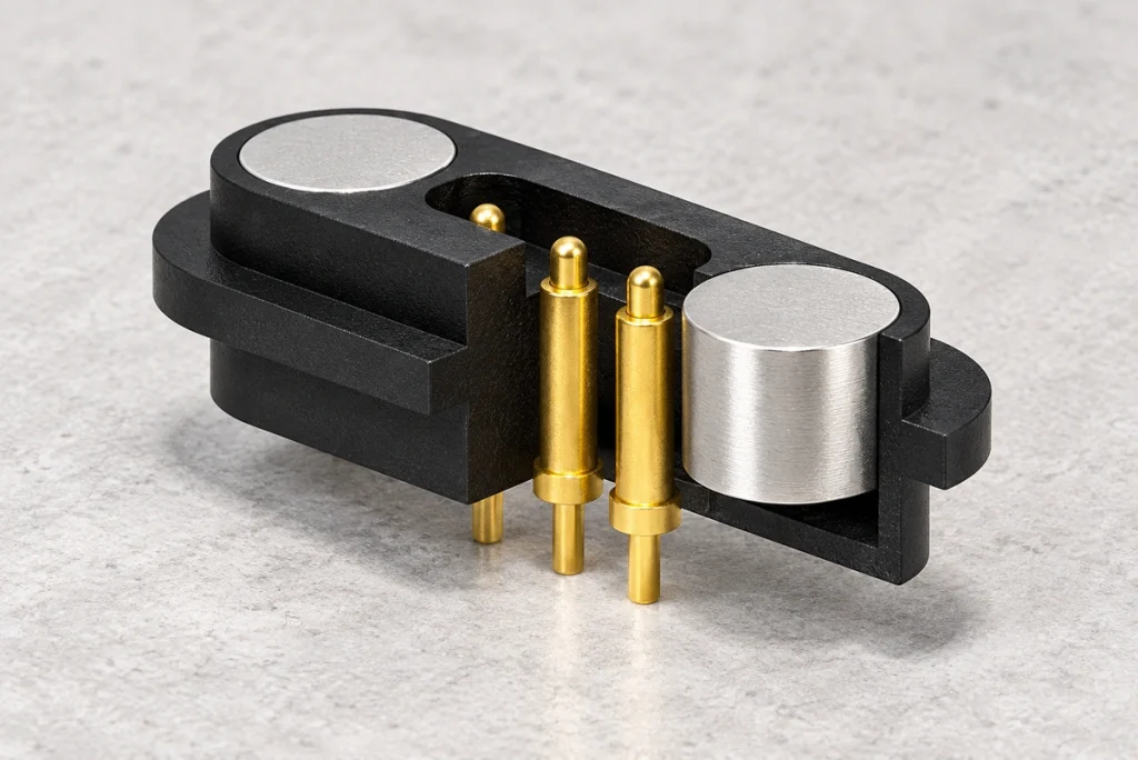
A pogo pin does not usually supply the magnetic attraction itself.
A magnetic pogo pin connector combines two roles:
magnetic pogo pin connectorMagnets: alignment and retention.
Pogo pins: the conductive connection.
As the charger and device approach, attraction can guide the mating parts toward the intended position.
A typical docking sequence is:
The magnets bring the parts into alignment.
↓
The pogo pins meet the pads.
↓
The pins enter their working compression range.
↓
Suitable alignment and pressure establish electrical contact.
↓
The compatible power source and charging circuit begin charging.
Guided docking can simplify connection because it reduces the need to insert a plug precisely.
It can be useful for products that are:
Compact, frequently charged, repeatedly docked, or designed with a sealed or clean exterior.
Magnetic attachment still does not prove that the electrical contact is reliable.
Evaluate all of these requirements:
Working stroke, spring force, contact alignment, magnetic retention, contact resistance and housing geometry.
contact resistanceInsufficient pin compression may cause weak or intermittent contact.
A misaligned pin may contact only a pad edge.
Coordinate the magnetic arrangement and mechanical geometry during design.
Engineering Selection Criteria
An OEM charging interface requires more decisions than the number of visible gold-colored contacts.
Review the parameters that influence reliable charging.
Required Current
Start with the current the interface must carry.
A low-power wearable may need little current, while an industrial cradle may have substantially different electrical demands.
Higher loads may call for larger contact surfaces, several power contacts, suitable conductor size and sufficient PCB copper. Multiple contacts still need a validated current-sharing arrangement.
Number of Contacts
For simple charging, two paths may be assigned to:
Power and ground.
Extra contacts can be assigned to functions such as:
Detection, identification, signals or communication.
Three or four contacts do not imply a universal assignment.
Define each function in the device design.
Working Compression
Mating must compress the plunger sufficiently within its specified operating range.
Too little compression can leave the connection unstable.
Excessive compression can increase stress and surface wear.
Include the final working position and tolerances in housing and PCB design.
Contact Spring Force
Spring force supplies pressure at the mating surface.
More force is not necessarily beneficial.
Excessive force increases mechanical load and can accelerate surface wear, especially across an array of pins.
Resistance at the Interface
Both charging and signal paths benefit from low, stable contact resistance.
An increase in resistance may result in:
Voltage drop, intermittent charging or additional heat.
Surface condition, plating, spring force, working stroke, contamination and mating life can all change resistance over use.
mating lifeThe Contact Finish
Many spring contacts have gold plating to help maintain electrical contact and resist corrosion.
Thickness, hardness, wear, nickel underlayers and the mating pad finish together affect the plating system's long-term performance.
For frequent docking or sweat and moisture exposure, assess the complete surface system rather than relying on the words 'gold plated.'
The Operating Environment
Design the contacts for the conditions the finished product will encounter.
For a wearable, consider:
Sweat and skin oils.
For medical equipment, consider:
Repeated cleaning and disinfection.
For outdoor equipment, consider:
Humidity, dust and water.
For an industrial cradle, consider:
Dust, vibration, repeated docking and the required service life.
These exposures affect the contact structure, plating, sealing, magnetic alignment and required mating-cycle performance.
Select an OEM contact within the full device design: space, current, contact count, PCB position, working height, force, mating life, plating, environment and mechanical structure all need review.
Magtor develops pogo pin and magnetic interfaces for charging and docking, including 2-, 3-, 4-, 5- and 6-contact designs and other multi-contact configurations according to power and signal needs.
2-pin, 3-pin, 4-pin, 5-pin, 6-pinIdentifying and Specifying the Contact Pair
The terms pogo pin, spring-loaded pin and spring-loaded contact commonly describe a small charging contact with a spring-driven movable plunger.
The fixed surface it touches is usually called a pad, mating contact or charging contact.
In earbuds, watches, docks, wearables, medical electronics and handheld equipment, spring contacts can provide repeatable connections while taking up small mechanical variations.
In a magnetic assembly, magnets guide and retain the parts; pogo pins provide the conductive path.
Reliable charging depends on current rating, stroke, spring force, resistance, plating, alignment, mating life and environment as well as contact count.
Recognizing the moving and fixed members helps identify a device's charging contacts and specify a suitable pair for a new design.
Questions About Charging Contacts
Does 'charging pin' always mean a pogo pin?
No. Charging pin is a broad description. A spring-loaded contact with a movable plunger is commonly called a pogo pin.
Are a watch's gold dots necessarily pogo pins?
No. Fixed gold-colored dots are usually mating pads. The moving spring contacts on the charger may be the pogo pins.
Can a pogo contact carry both power and data?
It can, where the electrical design supports that function. Power, ground, signals, identification and data are assigned through the device pinout rather than inferred from the contact itself.
What is the purpose of gold plating?
Gold helps stabilize contact and resist oxidation and corrosion. Select the complete plating system for cycle requirements, wear, environment and electrical demands.
What can make a charging contact fail?
Possible causes include dirt, corrosion, surface wear, insufficient compression, misalignment, mechanical damage or increased resistance. Identifying the actual fault requires checking the specific interface.