
Specifying a 4 Pin Magnetic Charging Cable for Your Device
Published on September 2, 2026
- The Four-Contact Cable Assembly
- How Magnetic Docking Establishes Contact
- Example Functions for Four Contacts
- Verifying Cable Compatibility
- Specifications for OEM Integration
- Typical Applications
- An OEM Selection Process
A 4 pin magnetic charging cable combines magnetic guidance with four conductive paths for power and optional signals. Unlike a standardized USB connector, it has no universal four-pin assignment. Match the pin functions, pitch, polarity, voltage and current, and dimensions to the device.
4 pin magnetic charging cableThe Four-Contact Cable Assembly
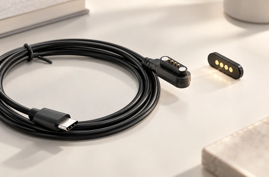
Its assembly brings together magnets, pogo pins or mating pads, cable conductors, and a USB or custom end connector.
Magnets guide the head into position. The four electrical contacts can be assigned to charging, signals, ID detection or control.
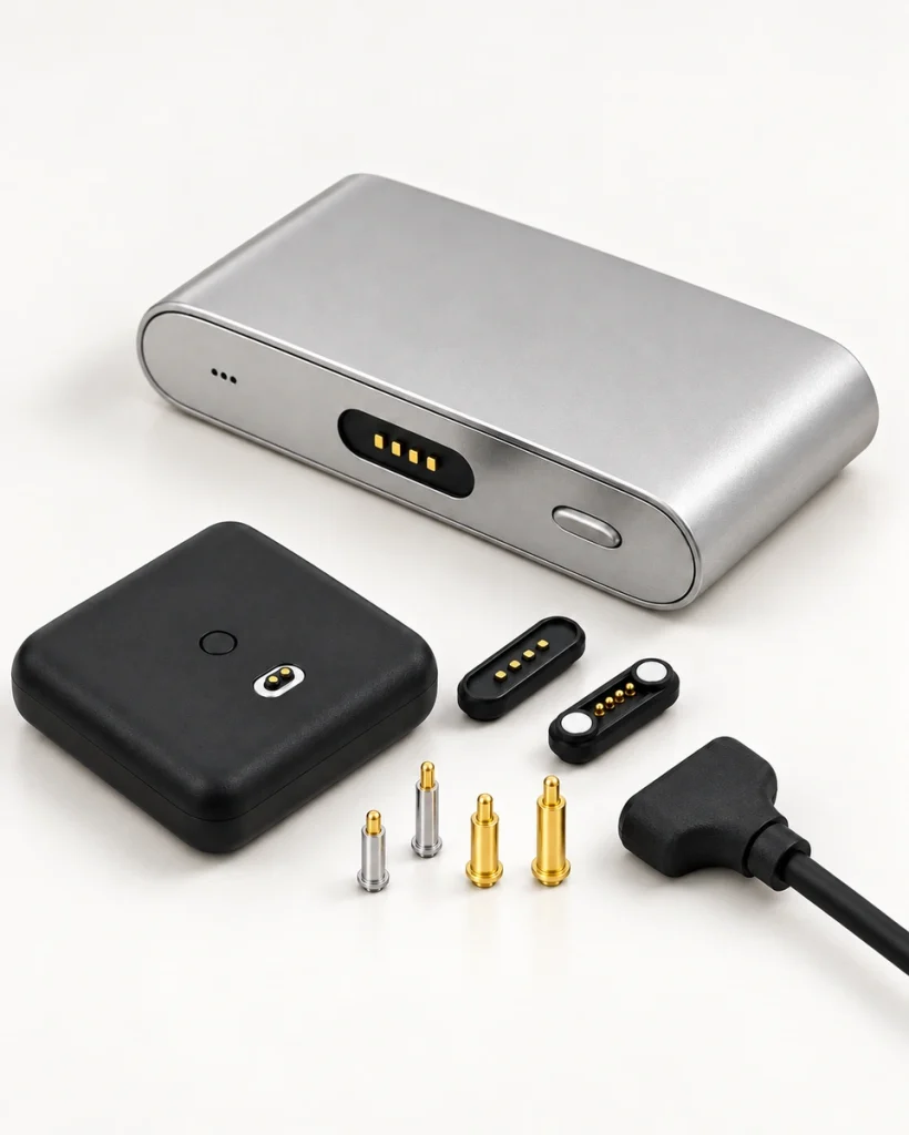
This arrangement can offer quick docking, less repeated plug-in wear and flexible integration into compact OEM products.
Explore the Magtor Magnetic Cable Connector range for other cable configurations.
Magtor Magnetic Cable ConnectorHow Magnetic Docking Establishes Contact
Docking combines two distinct roles.
Magnets align and retain the parts, while the spring contacts connect to the device-side conductive surfaces.
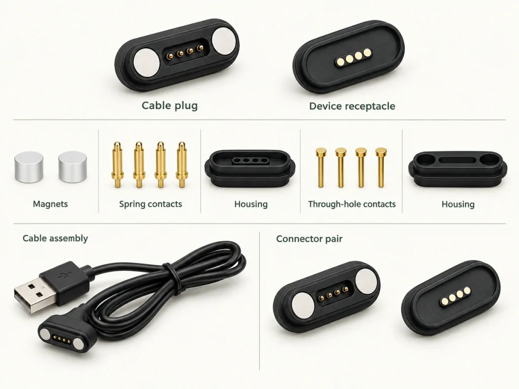
A typical conductive route is:
Power source → cable → magnetic contacts → device connector → PCB.
Magnetic force holds the parts together; the pin springs generate contact pressure. Evaluate these separate forces so attachment and electrical contact both suit the design.
Example Functions for Four Contacts
A four-contact magnetic cable does not have one fixed pinout.
Possible assignments depend on the product circuit, for example:
| Configuration | Example |
|---|---|
| Charging + Detection | V+ / GND / ID / Detection |
| Power + Data | Power / Ground / Signal / Signal |
| Parallel Power | V+ / V+ / GND / GND |
| Custom Control | Power / Ground / ID / Control |
Scroll horizontally to view every column.
Do not infer USB wiring from the four-contact count.
Power and data can share the interface only when the cable, PCB and electronics support the intended functions.
The 4 Pin Magnetic Connector Pinout and Wiring Guide provides further discussion of assignments.
4 Pin Magnetic Connector Pinout and Wiring GuideA USB-C source end also does not establish USB PD or high-speed USB data. Type-C identifies the connector interface; the complete electrical design determines charging and communication functions. Consult the USB Type-C specification from USB-IF for the standardized connector requirements.
USB Type-C specification from USB-IFVerifying Cable Compatibility
Similar-looking four-contact heads may still be incompatible.
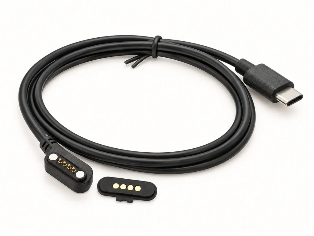
For a replacement or OEM assembly, verify:
Pin pitch: match the contact spacing.
Connector dimensions: confirm the housing fit and contact positions.
Pin assignment: match each electrical function.
Electrical polarity: align the positive, negative and signal paths correctly.
Magnetic polarity: confirm attraction in the intended mating orientation.
Voltage and current: use ratings suited to the device.
Working height: keep pogo compression within the operating range.
Cable end: select USB-A, USB-C, bare wire or a custom termination.
The main compatibility reminder is:
Matching contact counts do not establish interchangeable cables.
Specifications for OEM Integration
Prioritize specifications that affect reliability and integration in the OEM product.
Voltage and current ratings: define the needed power level and conductor dimensions.
Contact resistance: aim for a low, stable value to limit voltage drop and heating.
Pin pitch: align the contact layout with the PCB and mating connector.
Magnetic force: retain the connection while keeping removal practical.
Working stroke: provide the intended compression needed for stable electrical contact.
Cable length and gauge: longer runs or higher current may call for thicker conductors.
90° or 180° outlet: match the housing space and required cable route.
Mating cycles and water protection: review frequent docking, sweat, dust and moisture exposure.
Typical Applications
A four-contact cable can serve a product that needs additional functions beyond basic two-contact charging.
Application examples include:
Smartwatches and wearables: compact interfaces for daily charging.
Headphones and portable electronics: convenient magnetic docking.
Medical and personal-care devices: repeated charging in a compact layout.
IoT and smart products: power with detection or signal paths.
Charging docks: guided alignment and blind mating.
Industrial handhelds: quick connection with custom power or signal assignments.
The device's electrical and mechanical requirements still determine the cable, rather than its industry category alone.
An OEM Selection Process
Begin with the device specification before choosing a cable's appearance.
Work through these design steps:
Assign a function to each of the four contacts.
Confirm the voltage and current requirements.
Specify pitch and connector dimensions.
Choose USB-A, USB-C, bare wire or another end connector.
Set a 90° or 180° cable direction.
Define magnetic force and polarity.
Specify cable length and wire gauge.
Validate samples before mass production.
For a USB-C end, state whether the design needs charging alone, USB communication or another protocol. Use the USB-IF Type-C specification when defining a compliant Type-C interface.
USB-IF Type-C specificationSpecifying the Complete Cable
The Magtor 4 Pin Magnetic Charging Cable range offers configurable pin functions, end connectors, pitches, orientations and electrical requirements for OEM projects.
Magtor 4 Pin Magnetic Charging CableChoose a four-contact cable with its pinout, compatibility, current rating, pitch, magnetic layout, cable routing, and power and data requirements assessed together.
Questions About Four-Contact Charging
Are four-contact magnetic cables interchangeable?
Not by contact count alone. Cables may differ in pitch, dimensions, electrical polarity, magnet orientation and pin assignment. Check both mechanical and electrical specifications before replacing one.
Can the interface carry data as well as power?
Yes, where contact assignments and device electronics are designed for those functions. Four contacts alone do not establish USB communication or any particular transfer speed.
Does a USB-C end make it a standard USB-C cable?
No. Type-C may describe only one end. The magnetic interface's design and wiring must still support the required charging, USB data or other communication paths.
How can the four contact functions be identified?
Refer to the device schematic, connector drawing or cable specification. Do not assume VCC, GND, D+ and D− are the assignments: a magnetic interface may use a custom pinout.
What does an OEM need to specify for customization?
Provide voltage, current, pin assignment, pitch, dimensions, magnetic force, length, wire gauge, cable direction and the required USB-A, USB-C, bare-wire or custom end.