
Four-contact Magnetic Connector Pinouts and Wiring
Published on July 16, 2026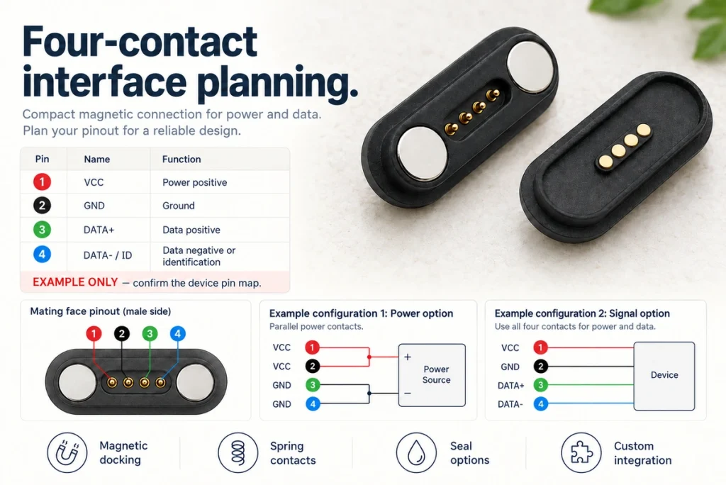
- The Four-contact Magnetic Arrangement
- Example Contact Assignments
- Power and Data Wiring Examples
- PCB Integration Requirements
- Polarity and Mating Orientation
- Comparing Two and Four Contacts
Four-contact magnetic interfaces use magnetic guidance and conductive contacts to provide the paths assigned by the product design. This guide covers example pinouts, power and data wiring, PCB integration and orientation checks for smart and industrial equipment. Confirm the actual connector drawing before using any example assignment.
The Four-contact Magnetic Arrangement
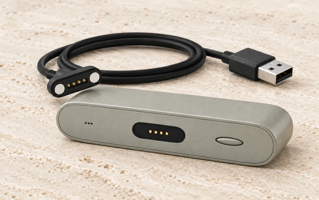
The assembly combines four electrical contacts with magnets and locating geometry. Pogo contacts may provide spring compliance while the magnetic arrangement assists guidance and retention.
Four-contact magnetic interface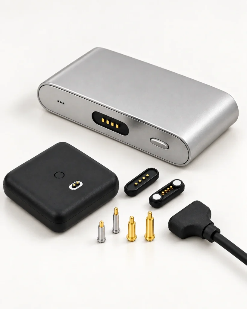
Potential integration benefits include:
Quick magnetic attachment.
Blind mating within the specified approach range.
Less insertion-related wear.
Compact placement where the rating and spacing permit it.
Power and supported signals through the verified contact allocation.
One common structure uses magnets, a plastic housing and spring contacts. Other arrangements are possible, so use the selected assembly’s drawing rather than assuming every four-contact interface has the same construction.
Example Contact Assignments
Choose the contact assignment from the required power and communication functions. Four contacts do not define a universal pinout or protocol.
An Example Four-contact Assignment
| Contact | Example function | Assignment condition |
|---|---|---|
| Pin 1 | VCC | Positive supply in this example |
| Pin 2 | GND | Ground or return path |
| Pin 3 | DATA+ | A data path where the implemented interface uses it |
| Pin 4 | DATA− or a custom ID path | DATA− belongs to a matching data arrangement; using this path for identification instead is a different custom allocation |
Scroll horizontally to view every column.
A power-and-data example uses two power paths and two data paths. Other assignments are possible, but all mating halves, cable conductors and circuitry must follow the same verified definition. Do not interchange DATA− and ID without redesigning the implemented function.
Power and Data Wiring Examples
Power-only Allocation
A charging-only arrangement may use two contacts for supply and two for return. Verify current sharing and the complete termination path before relying on a combined capacity.
One example is:
| Pin 1 → VCC+ | Pin 2 → VCC+ |
| Pin 3 → GND | Pin 4 → GND |
Scroll horizontally to view every column.
Possible design goals include:
A current path that meets a higher load.
Lower combined path resistance where current shares as intended.
Temperature rise within the required limit.
This arrangement may be considered for portable electronics, smart devices and charging docks with a matching power-only requirement.
Power and Supported Data
For an implemented interface using a supply, return and data pair, the example mapping is:
| Pin 1 → VCC | Pin 2 → GND |
| Pin 3 → DATA+ | Pin 4 → DATA− |
Scroll horizontally to view every column.
Potential applications include suitable smart wearables, medical equipment and industrial handhelds. Data capability and qualification depend on the connected circuitry, layout and complete interface.
PCB Integration Requirements
Select the intended pogo-contact termination, such as SMT or through-hole, and review any mounting screws or other supports. PCB layout and housing retention need to accommodate both electrical paths and mating loads.
Contact Pitch
Pitch affects:
PCB routing.
Circuit boardThe installed connector size.
Mechanical support and spacing.
Current Requirements
Review the current path against:
Contact diameter and conductive geometry.
Contact resistance.
The coating system.
Spring-contact structure and working force.
Thermal conditions in the product.
Contact Stability
Features and evidence to evaluate include:
An appropriate gold-plating system.
Resistance to the specified corrosion exposure.
Retention sufficient for the required engagement.
Contact pressure within the working limits.
Polarity and Mating Orientation
Magnetic guidance can help locate the halves, while the final orientation determines whether their electrical assignments meet correctly.
Review both magnetic polarity and mechanical locating:
Magnet Polarity
An incorrect arrangement may produce:
Repulsion in the intended mating position.
An unintended mating orientation.
Misaligned contact faces.
Mechanical Locating
Possible design features include:
A circular magnetic arrangement with the required orientation control.
Keyed housing geometry.
An asymmetric contact layout.
Check these features for reverse-mating protection and correct contact engagement. One-handed attachment may be convenient, but magnetic attraction alone does not establish correct polarity or automatic safe charging.
Comparing Two and Four Contacts
| Feature | Two-contact charging example | Four-contact example |
|---|---|---|
| Power | Supply and return paths | Supply and return paths |
| Data | No separate data paths in the basic power-only allocation | Possible with the required contact assignment and circuit design |
| Signal | No additional separate signal path in that allocation | Additional paths can implement compatible signals |
| Layout flexibility | Application-specific geometry | Application-specific geometry and assignment |
| Typical function example | Charging | Charging plus an implemented communication function |
Scroll horizontally to view every column.
Wearables — smartwatches, fitness trackers and medical wearables, with the actual load and qualification defined.
Smart-home products — sensors, smart locks and charging stations with a matching power and signal allocation.
Industrial products — handheld terminals, test instruments and portable controllers with the required electrical and mechanical validation.
Pinout Questions
Is There a Universal Four-contact Pinout?
No. VCC, GND, DATA+ and DATA− form one possible assignment. Use the exact model drawing and implementation; a custom layout may define different functions.
Can Four Contacts Carry Power and Data?
Yes, where the allocation and electrical design implement both functions. Contact count alone does not establish a data protocol, rate or charging capability.
Is Every Four-contact Interface Sealed?
No. A suitably designed model may target IP67 or IP68 in a specified assembly state. Confirm the relevant protected parts and test conditions for outdoor or industrial use.
Can the Contact Assignment Be Customized?
A supplier may support changes to pin layout, verified current, magnetic force, cable assembly and dimensions. Agree the matching circuitry, drawings and validation for any custom assignment.
Conclusion
Four contacts can provide a simple power-and-data arrangement when the assigned functions match the device. Confirm the pinout, mounting, orientation and performance requirements before wiring the assembly. Magtor can discuss a suitable standard or custom interface and the tests needed for your application.
Magtor