
Magnetic Cable or Conventional Connector? A Device-Interface Comparison
Published on August 24, 2026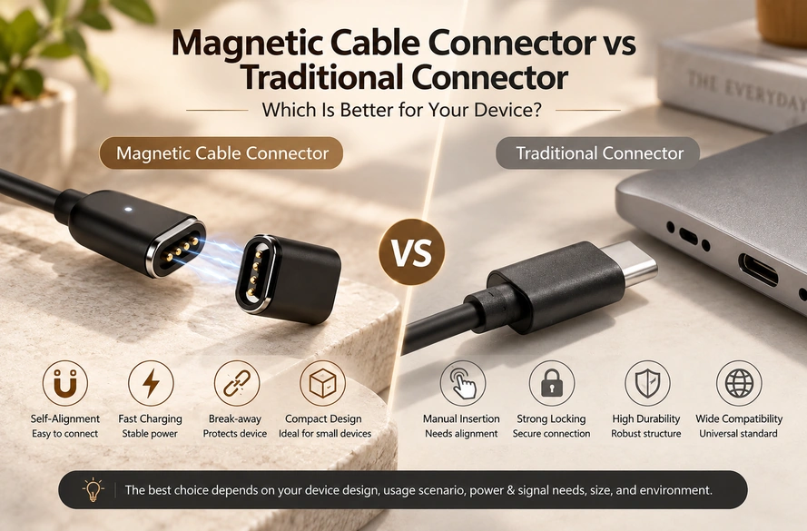
- Mating architecture and construction
- Engagement, removal and cable routing
- Wear, enclosure space and sealing
- The complete power and signal route
- Compatibility, customization and cost
- Choosing for the device
A magnetic cable can offer guided docking, a dedicated envelope and controlled removal. A suitable conventional interface can provide a positive lock and standardized replacement parts. Compare the actual mating duty, load, signals, space and exposure; neither category is preferable for every device.
Mating architecture and construction
A magnetic cable is typically a complete assembly: a guided mating head, conductive contacts, conductors and an opposite end such as USB-A, USB-C, terminals or a dedicated connector.
complete magnetic cable assembly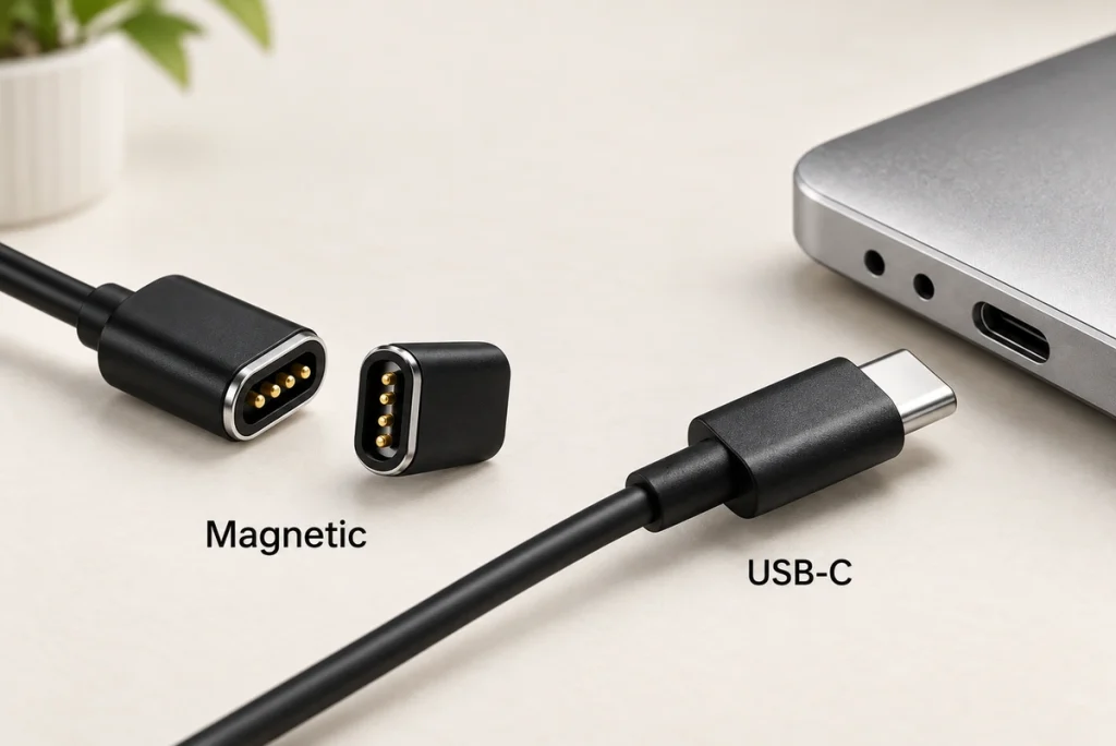
At the device, attraction assists positioning and spring contacts compress against matching surfaces. The housing controls final alignment and working travel for the electrical connection.
Conventional USB, DC barrel and many industrial interfaces instead use an inserted plug and receptacle, with positioning supplied by the user or docking structure. Their retention arrangements vary by connector family.
The mating action is the primary architectural difference.
| Design factor | Magnetic cable assembly | Conventional interface |
|---|---|---|
| Mating method | Guided magnetic engagement and contact compression | Insertion into a matching receptacle |
| Alignment | Guidance within the designed capture range | User positioning or mechanical guidance |
| Blind mating | Possible with suitable capture and mating geometry | Depends on the selected connector and dock |
| Break-away | Possible with defined retention and release conditions | Not inherent in many inserted plug forms |
| Device interface | Dedicated geometry can be developed | A standard or dedicated geometry, depending on the family |
| Pin configuration | Functions assigned for the product | Functions defined by the selected standard or device |
| Cable termination | Defined USB-A, USB-C, wire or dedicated end | The end required by the selected interface |
| Compatibility | Generally a dedicated matching pair | Depends on the implemented standard and functions |
| Positive locking | Magnetic retention is not a positive mechanical lock | A lock is available in some connector families |
Scroll horizontally to view every column.
Magtor can review spring-contact mating with guided attachment, orientation control and intended release behaviour. Verify the contact pressure, electrical mapping and removal load for the proposed assembly rather than treating those possibilities as universal protection.
For OEM work, compare the complete device interfaces: housing integration, mating action, conductors, electrical functions and the supported replacement arrangement.
Engagement, removal and cable routing
A typical conventional mating sequence is:
Position → Insert → Engage
Insertion brings the contacts together, with retention provided by the family’s friction, compliant contacts or locking structure.
A typical magnetic mating sequence is:
Approach → Magnetic guidance → Contact compression → Conductive engagement
Attraction helps position the cable head. Once the housing reaches its intended mating state, the spring contacts engage their targets and provide the assigned supply or signal paths.
Consider these handling differences:
Guided mating when the interface is difficult to see
Guidance may help a wearable dock, medical product, handheld terminal or small charging station where the mating area is not easily visible. Validate handling and device-specific safety for the application.
Defined release behaviour
An accidental pull on an inserted plug may load the receptacle and enclosure. The effect depends on the connector, cable and support of the device.
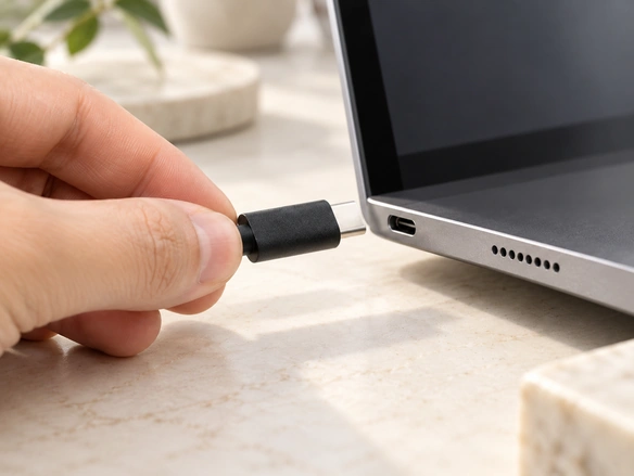
A magnetic joint can be designed for a specified release force and direction. This may be useful for tabletop or wearable products where cable loading matters, but it does not guarantee that a pull cannot drag or damage the device.
Greater retention is not automatically more suitable.
Balance it with:
Device weight and support
Cable stiffness
Mating-head envelope
Required holding load
Intended manual removal
Spring-contact reaction
Required release behaviour
90° and 180° cable exits
Cable routing is another part of the mechanical integration.
Magtor can review 90° or 180° exits for a magnetic cable configuration. Those angles describe routing, not permission to reverse electrical mating.
90° and 180° magnetic cable exit optionsA 90° exit may suit limited rear clearance or a cable routed along the enclosure. Check its bend radius and support near the head rather than assuming it eliminates bending stress.
A 180° straight exit may suit a clear route behind the device. Confirm the available space and the loads that route applies to the joint.
Conventional connector families can also offer straight or angled forms. Their available geometry depends on the chosen receptacle and plug series.
A dedicated magnetic assembly can be evaluated for housing shape, exit angle and mating direction within the product’s available envelope.
Wear, enclosure space and sealing
Neither mating category guarantees a longer life. Assess the wear and fault mechanisms of the actual assembly.
Inserted interfaces can wear at contacts, plug and receptacle surfaces or retention features during repeated mating. The relevant duty and life depend on the connector family and operating conditions.
A magnetic spring-contact pair avoids deep plug insertion but still requires assessment of:
Spring fatigue
Contact-finish wear
Surface contamination
Incorrect installed contact height
Cable-flexing duty
Changes in retention
Damage to mating surfaces
Available enclosure space
Surface contacts may be useful where a deep receptacle cannot fit, subject to the full housing and working-travel requirements.
A shallow device-side pad area can pair with a spring-loaded cable head. Include magnetic space, compression, stops and the complete mating gap in the envelope.
Possible space-sensitive applications include:
Smart watches
Hearing-device interfaces
Smart glasses
Compact medical products
Sensor products
Portable terminals
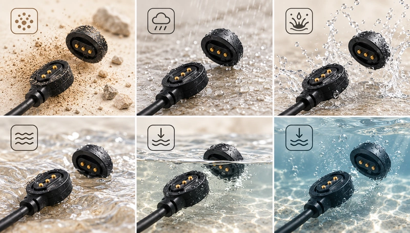
Sealing requirements
Magnetic guidance does not itself seal the device.
Protection depends on the implemented structure, including:
The contact housing
The board mounting and sealing interface
Required O-rings or gaskets
Potting where used
Molded sealing features where used
The cable entry
A suitable exposed-contact finish
The complete device enclosure
IEC 60529 classifies enclosure ingress protection. Confirm the stated classification, test conditions and assembly boundary for the actual product; the reference alone establishes no product rating.
IEC enclosure ingress classificationA flat magnetic mating area may help some enclosure designs. Conventional interfaces can also achieve specified ingress protection through suitable sealed receptacles, caps, gaskets or locks. Compare the complete tested structures.
Avoid this unsupported assumption:
Magnetic attachment does not guarantee waterproofing, and conventional insertion does not exclude it.
Ask instead:
Which complete interface can meet the specified ingress requirements within this enclosure?
For moisture, sweat or outdoor use, evaluate a dedicated sealed structure and the appropriate contact materials. Validate ingress and chemical exposure separately rather than assuming a general magnetic cable covers both.
sealed magnetic connector rangeThe complete power and signal route
Compare actual electrical implementations rather than deriving performance from the mating category.

Magnetic engagement alone establishes neither better nor worse electrical capability. Review the complete conductive route:
PCB → Device-side contact → Spring-contact interface → Cable conductors → Opposite termination
Contact count and allocation
Magtor can review two-, three-, four-, five- or eight-contact cable layouts according to the required circuit paths. The corresponding connector and cable ranges provide a configuration starting point, not a universal assignment or protocol guarantee.
two-contact magnetic assemblyThree-contact magnetic assemblyfour-contact magnetic assemblyfive-contact magnetic assemblyIllustrative OEM allocations are:
| Pin Count | Illustrative allocation |
|---|---|
| 2 Pin | Power + Ground |
| 3 Pin | Power + Ground + ID/Detect |
| 4 Pin | Power + Ground + 2 Signal Paths |
| 5 Pin | Power + Ground + Data/ID/Control |
| 8 Pin | Mixed Power + Multiple Signal Paths |
Scroll horizontally to view every column.
Approve the mapping for the actual device; the table is not a wiring standard.
One four-contact example is:
V+ / GND / Data+ / Data−
A different four-contact product might allocate:
V+ / GND / ID / Control
The four-contact wiring guide explains why supply, signals, numbering and mating views must follow the device architecture rather than contact count alone.
four-contact allocation and wiring guidePower-path requirements
For a magnetic cable, assess:
Contact diameter
Contact resistance
Contact finish
Number of assigned supply contacts
Conductor cross-section
Cable length
Termination design
Temperature rise
Parallel contacts may be considered for additional supply paths. Verify sharing and the full cable’s thermal behaviour; the allowable current does not simply multiply with the number of contacts.
An established standard power interface may be practical where it meets the product’s load, space and compatibility requirements.
USB-C can carry an implemented USB Power Delivery architecture when the source, cable, receiving device and controls meet the applicable requirements. The connector shape does not establish every PD feature or any rating for this magnetic assembly.
USB Power Delivery architectureData and application signals
A magnetic cable can provide assigned data paths, but multiple contacts do not establish a protocol or speed. Validate the actual interconnect and electronics.
Signal-path inputs include:
The electrical contact map
Signal return and reference placement
Contact transition geometry
Required cable impedance
Shielding where required
Cable length
Inter-path crosstalk
PCB routing
A validated standard series may simplify high-speed interoperability. Confirm the intended implementation rather than generalizing that advantage to every conventional connector.
For USB-C, connector form and supported functions need particular distinction.
A USB-C end does not mean the whole cable implements every data mode or PD function. USB-IF defines requirements for the relevant connector and cable implementation; verify conductors, control functions and compliance for the intended equipment.
USB-IF Type-C connector and cable requirementsA dedicated layout may be practical for basic charging or defined low-speed signals, subject to its complete electrical review.
High-speed USB, video and other controlled-impedance functions require validation across the contact transition, conductors, terminations and PCB routing.
Compatibility, customization and cost
A suitable standardized interface can simplify matching and replacement compared with a dedicated mating pair.
Widely adopted USB-C forms offer replacement choices from multiple suppliers. The required data and power functions must still match; a published mating form does not make every cable functionally equivalent.
This may reduce:
Interface-development work
Custom tooling
Complexity of sourcing matching replacements
Dependence on one dedicated mating design
A magnetic cable offers another route where the product needs a dedicated geometry or allocation.
Evaluate whether developing the mating pair for the device is preferable to adapting the device around an existing part.
Inputs for a dedicated assembly include:
Contact count
Contact spacing
Electrical allocation
Magnet polarity
Retention and release targets
Installed contact height
Available envelope
Housing material
Cable length
Conductor size
Jacket requirements
USB-A termination
USB-C termination
Bare-conductor termination
Dedicated opposite-end connector
90° cable outlet
180° cable outlet
Specified sealing structure
Magtor can review these inputs for a magnetic cable project, with configuration feasibility and validation agreed for the product.
USB-A and USB-C ends
USB-A may suit a compatible conventional source or basic charging architecture. Confirm the source and receiving-device requirements.
For USB-C equipment, specify whether the cable needs basic supply, USB data, Power Delivery, CC functions or another implemented feature. Select and validate the complete architecture accordingly.
Mechanical fit at the USB-C end is only one requirement; electrical functions must match too.
Conductor size
Select conductors for the full circuit and mechanical duty.
AWG is a common way to identify conductor size. ASTM B258 addresses nominal diameters and areas of solid round AWG conductors. It is not a universal stranded-cable current-rating table; verify the actual conductor construction and application limits.
ASTM solid-round AWG dimensional referenceA higher-current path may need a larger conductor, while a low-current signal may permit a smaller one. Confirm voltage drop, heating and termination requirements for each.
Changing conductor size also affects:
Overall cable diameter
Cable flexibility
Molded transition dimensions
Strain-relief design
Handling and loading on the device
Assess electrical load and mechanical integration together when selecting wire size.
Required cable length
Increasing length adds resistance for otherwise comparable material, cross-section and temperature, and can increase voltage drop under load.
The same contact head therefore needs separate review with:
A short cable under a low-current load
A longer charging cable
A higher-current circuit
Define length with conductor size, current and permitted drop. Include routing convenience, but do not use it as the only criterion.
Total interface cost
A suitable existing connector may reduce cost where:
The required interface already follows a standard.
No dedicated mating geometry is needed.
Production and replacement requirements favour broad compatibility.
Custom housing, magnetic placement, molding or wiring can add initial engineering and tooling. Request a configuration-specific quotation rather than assuming a fixed premium.
That investment may be justified if it meets space, docking, routing or repeated-connection needs in the complete device. Confirm the actual benefits rather than promising savings.
Compare development, integration, validation and use costs as well as the connector’s unit price.
Choosing for the device
There is no universal category winner.
Consider magnetic cable construction for requirements such as:
Repeated charging or docking
Guided alignment
Mating where visibility is limited
Defined magnetic release
A compact enclosure
A dedicated contact allocation
Product-specific power and signal paths
A dedicated mating envelope
90° or 180° exit routing
Defined cable length or conductor size
A specified USB-A, USB-C or dedicated end
USB-A or USB-CSurface contacts integrated with a validated sealed enclosure
Consider a suitable conventional interface for:
Required standardized compatibility
Matching standard replacement cables
A validated high-speed protocol interface
Positive mechanical locking where needed
A defined standardized service connection
Reducing dedicated tooling
Interoperability among compatible suppliers
The following are configuration starting points to validate:
| Device Requirement | Configuration to evaluate |
|---|---|
| Basic charging only | A suitable two-contact magnetic cable |
| Charging + detection | A suitable three-contact magnetic cable |
| Power + two signal paths | A suitable four-contact magnetic cable |
| Power + data + ID/control | A suitable five-contact magnetic cable |
| Multiple power/signal paths | A suitable eight-contact magnetic cable |
| Tight side clearance | A 90° exit with the required bend clearance |
| Open straight routing | A 180° exit with the required rear clearance |
| Existing USB chargers | A compatible USB-A end with defined functions |
| Modern charger ecosystem | A compatible USB-C end with defined functions |
| Custom equipment | The required matching terminal, bare conductors or dedicated end |
Scroll horizontally to view every column.
Before finalizing, review voltage, continuous and peak current, pinout, length, wire size, PCB position, enclosure thickness, retention, exit direction and environment for the actual assembly.
Guided convenience or standardization alone cannot determine the choice. Both need to meet the device’s complete operating requirements.
Select and validate the interface for electrical functions, fit, exposure and handling in the representative product.
Magtor can review a dedicated magnetic cable for the enclosure and PCBA, including two-, three-, four-, five- or eight-contact layouts, suitable length and conductors, a USB-A, USB-C or dedicated end, and 90° or 180° routing. Confirm the configuration and its validation plan before production.