
2-Pin vs 3-Pin Magnetic Connectors: Functions Before Contact Count
Published on August 21, 2026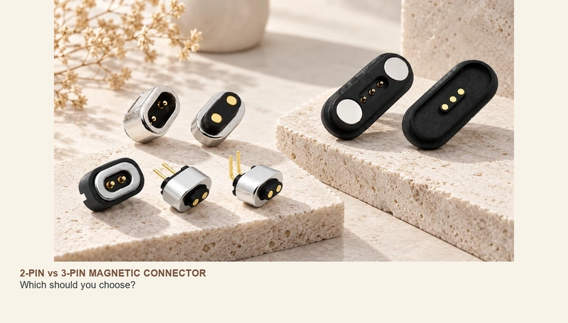
- Contact count and independent functions
- Typical allocations and their limits
- Charging, power and added signals
- Packaging, routing and cost
- Application examples
- Selection checks for the device
- Choosing the required contact count
A two-contact magnetic pair often provides a supply path and return. A third contact can add a defined detection, identification, sensing, control or other signal function. Choose from the actual circuit, allowable current, envelope and PCB layout rather than assuming more contacts provide better charging.
Contact count and independent functions
Both are magnetic interfaces in which attraction assists placement while conductive contacts, often spring-loaded, form the electrical paths.
magnetic contact interfacesAn additional separately wired contact can provide another independent circuit path.
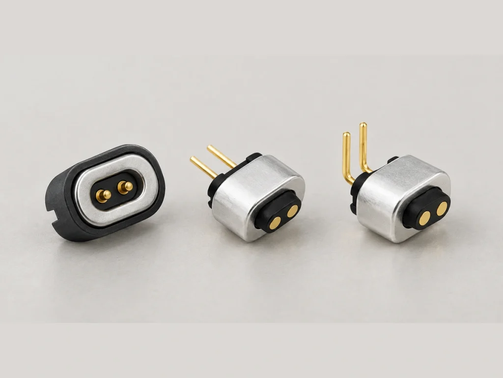
A common two-contact charging example assigns:
Two-contact magnetic pairPin 1: V+
Pin 2: GND
This may provide the required power connection where no separate signal is needed and the complete charging and protection design supports it.
A three-contact example can add one path:
Three-contact magnetic pairPin 1: V+
Pin 2: GND
Pin 3: Defined Detect, ID or Signal function
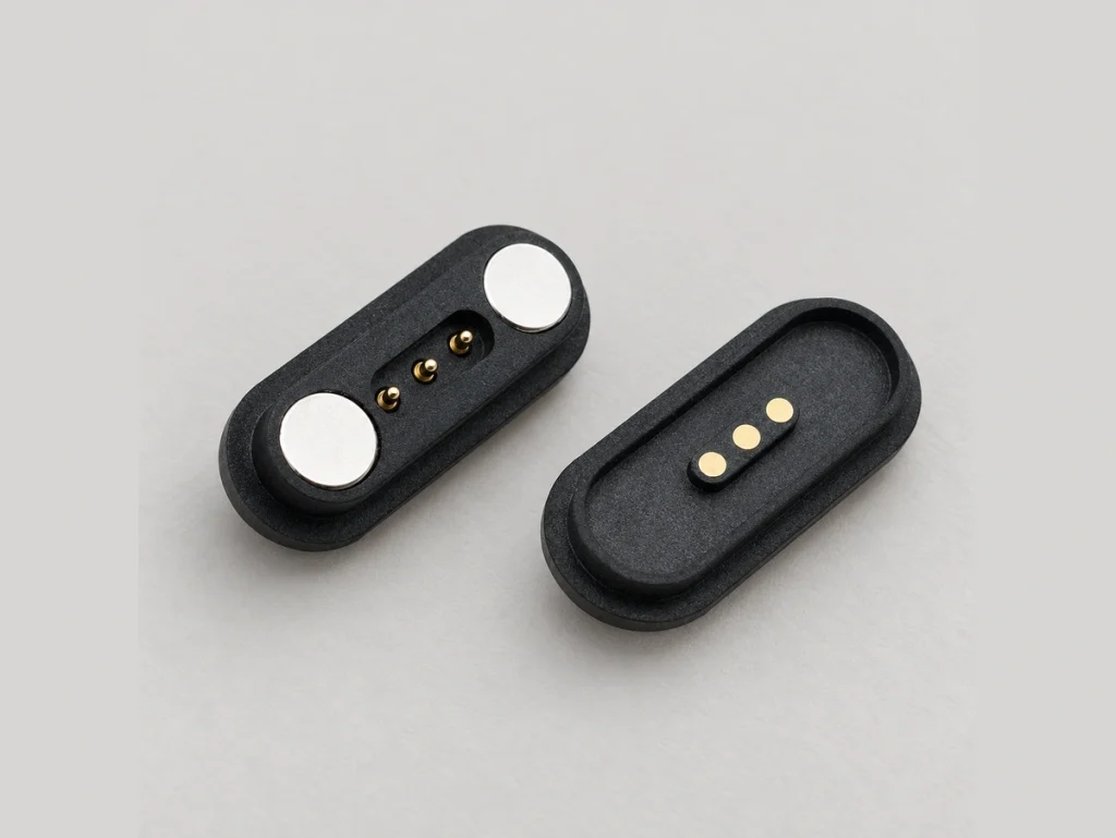
There is no universal three-contact magnetic pinout. Define the added function and the matching electrical behaviour at both ends.
Choose the count from the required functions. The magnetic contact-count guide applies that approach to assemblies with more contacts as well.
magnetic interface contact-count guideTypical allocations and their limits
Define the role of each path before deciding how many contacts are needed.
A simple rechargeable product may use this illustrative DC allocation:
| Pin | Illustrative two-contact function |
|---|---|
| Pin 1 | V+ |
| Pin 2 | GND |
Scroll horizontally to view every column.
The positive path and return may suit basic power or charging where the device needs no additional contact function.
A third separately wired contact provides another possible allocation:
| Pin | Illustrative three-contact function |
|---|---|
| Pin 1 | V+ |
| Pin 2 | GND |
| Pin 3 | A defined Detect, ID, Sensor or Control function |
Scroll horizontally to view every column.
That extra path may detect engagement, identify an accessory, monitor temperature, enable charging or carry a low-speed signal where the electronics implement the required function.
Three contacts do not inherently provide data communication. The circuits on both halves define and support the added function.
Document the approved mapping, mating views and complete cable wiring before PCB layout or conductor termination is finalized.
For USB or another standardized communication interface, implement and validate the required architecture. An extra contact alone cannot establish the protocol requirements published by USB-IF.
USB-IF protocol specificationsCharging, power and added signals
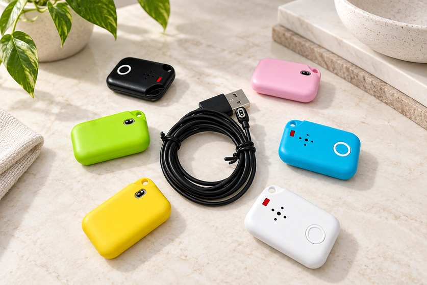
For a power-only requirement, two contacts may be the simpler allocation.
A positive path and return can complete the supply circuit for suitable rechargeable devices. Fewer paths may simplify routing and packaging, while current, protection and conductor requirements remain to be confirmed.
Consider a third path when the system has an additional defined electrical function.
Illustrative requirements are:
Power-only charging
V+ + GND → Two contacts may suffice for the defined power circuit.
Charging with engagement detection
V+ + GND + Detect → Three contacts may suit the implemented detection circuit.
Charging with accessory identification
V+ + GND + ID → Three contacts may suit the implemented identification circuit.
Power with several data or control paths
Consider four or more contacts after identifying every function and return.
Contact count alone does not set the allowable current.
A three-contact assembly is not inherently higher-current than a two-contact one. Assess diameter, conductive material, spring force, finish, compression, cable size, contact resistance and installed temperature rise for the assigned load.
mating contact resistanceInterface resistance adds voltage drop and heating as current increases. Include it in the full power-path and thermal assessment.
Packaging, routing and cost
A two-path allocation can reduce circuit complexity where it covers the required functions.
With fewer paths to route, the PCB and mating layout may be simpler. Actual size still follows the contact, magnetic and mechanical requirements.
| Design input | Two-contact magnetic pair | Three-contact magnetic pair |
|---|---|---|
| Illustrative function | Defined supply or charging paths | Supply plus one defined auxiliary function |
| Pin assignment | Two allocated paths | One additional allocation option |
| PCB routing | Potentially fewer paths to route | An additional path to integrate |
| Connector size | May be easier to package with fewer paths | May need more room, depending on the design |
| Circuit design | Supply and protection circuitry as required | Added detection or control circuitry where implemented |
| Cost | May be lower for otherwise comparable requirements | May increase with the added function and construction |
| Customization | Mechanical customization remains possible | One additional electrical-function option |
Scroll horizontally to view every column.
Two contacts do not guarantee a smaller or cheaper assembly.
Other cost inputs include:
Magnet dimensions and retention target
Housing material
Specified contact finish
Required current capacity
Sealing construction
Mounting arrangement
Cable construction
Order and production quantity
Required tooling
Pitch, magnet placement, working height, housing geometry and mechanical support all affect the final envelope. Compare actual layouts rather than contact count alone.
Review the connector with its complete mechanical integration and electrical circuit. That is the basis for a meaningful comparison of size, function and cost.
electrical interconnect assemblyApplication examples
Two-contact applications
A two-contact supply layout can be useful for a compact device whose interface only needs power, subject to the load, charging and environmental requirements.
Possible applications include:
Smartwatches
Fitness trackers
AI smart glasses
Pet trackers
Smart mugs
Electric toothbrushes
Small rechargeable products
LED products
Compact charging cradles
Magtor can discuss two-contact layouts for devices where a small mating area and simple supply connection are priorities.
Three-contact applications
A three-contact layout can suit supply paths with one additional defined function.
Possible applications include:
Smart charging cradles
Sensor products
Medical electronic devices
Connected home equipment
Wearable products
Handheld equipment
Device-identification connections
Charging with engagement detection or control
The extra path may cover that function without moving to a larger contact count. Final size and practicality still depend on the complete layout.
Exposure requirements apply to either count. For rain, sweat, dust, cleaning fluids or outdoor use, assess sealing, housing integration and contact materials for the actual environment. A magnetic assembly needs validation as part of the device.
sealed magnetic connector rangeIEC 60529 classifies enclosure dust and water protection. Confirm the applicable test conditions and assembled-product evidence; an IP statement does not establish every corrosion or chemical-exposure requirement.
IEC ingress-protection classification referenceSelection checks for the device
Begin with the required functions:
Consider two contacts when:
Only a positive supply path and return are needed.
The interface primarily serves the defined charging circuit.
Available board space is limited.
A compact mating area matters.
No separate detection, identification, sensing or control path is required.
Reducing unnecessary circuit and structural complexity is a priority.
Consider three contacts when:
Supply and return need one extra independent path.
The product needs engagement detection.
The accessory or charger must be identified.
A sensor or temperature-monitoring path is required.
Charging enable or another control path is required.
A defined future function justifies an additional contact.
Also confirm these eight interface inputs:
Voltage and current: Define operating voltage and continuous and peak loads, then verify the complete assembly limits.
Electrical allocation: Assign every path, with the mating views and numbering recorded.
Contact resistance: Set acceptable initial and aged values for the required power and signal performance.
Retention: Maintain engagement while keeping intended removal manageable; verify force and pull direction.
Working height and travel: Keep spring contacts within the recommended compression range across the assembly tolerances.
Packaging: Review the available PCB and enclosure envelope and any device changes needed for integration.
Mounting: Evaluate SMT, through-hole electrical termination, mechanical screw fixing, wire termination or housing integration as applicable. Mechanical and electrical methods may be combined.
Environment and duty: Define water, sweat, dust, corrosion, vibration and mating-cycle requirements, with appropriate separate validation.
For OEM work, contact count is one input. Enclosure dimensions, pitch, magnet polarity, working height, retention, finish, cable exit and mounting can also require a dedicated design.
Where a suitable standard part does not fit, evaluate an assembly developed around the device envelope. Confirm feasibility; customization does not guarantee that the PCB or enclosure will need no changes.
Choosing the required contact count
Two contacts may cover a simple supply-and-return charging requirement, with its current capacity, protection and environmental needs verified.
Three contacts add an allocation option for detection, identification, sensing, control or another defined function supported by the product’s electronics.
Neither contact count is universally preferable.
Choose the paths needed to implement all required functions, then verify load capacity, size, mechanics, exposure and cost. Avoid adding contacts without a defined role.
Magtor can review a dedicated contact map, housing, retention, sealing and cable assembly for the specific product requirements.
MagtorFrequently asked questions
Can two contacts carry data?
Two paths are usually allocated to supply and return in a charging interface. Specialized signalling schemes are possible, but separate power and communication paths often call for more contacts. Confirm the actual electrical architecture rather than assuming data is impossible or inherently supported.
Will a third contact increase charging speed?
No increase follows from contact count alone. Charging current and speed depend on the circuit, contact dimensions and material, resistance, cable and thermal limits, together with the source and receiving device.
Does adding a contact always increase the size?
It may, but not necessarily. Pitch, magnet layout, housing, contact diameter, mounting and retention requirements determine the final envelope.
Can either count be integrated into a sealed device?
Both can form part of a sealed design. Verify the housing, seals, installation, tolerances and exposure conditions in the representative assembly. Contact count alone establishes no ingress classification.
Can a three-contact assembly replace a two-contact one?
Only after confirming a compatible mechanical and electrical design. Define the added function and verify PCB fit, housing, polarity, magnetic arrangement, current limits and the mating pair. A similar appearance does not make it a direct replacement.