
Designing a Magnetic Power Connector: From Pinout to Validation
Published on August 13, 2026
- The components and their roles
- Choosing power contacts
- Magnet layout and polarity protection
- Housing geometry and working height
- Power-path protection
- Validation before production
A magnetic power interface uses magnets to assist engagement while conductive contacts carry electricity. Development brings together the contact selection, retention and release forces, housing, working height, polarity controls and electrical protection, followed by validation of the complete assembly.
magnetic power interfaceThe components and their roles
A typical interface has four principal parts: conductive contacts, magnets, an insulating housing and matching contact surfaces.
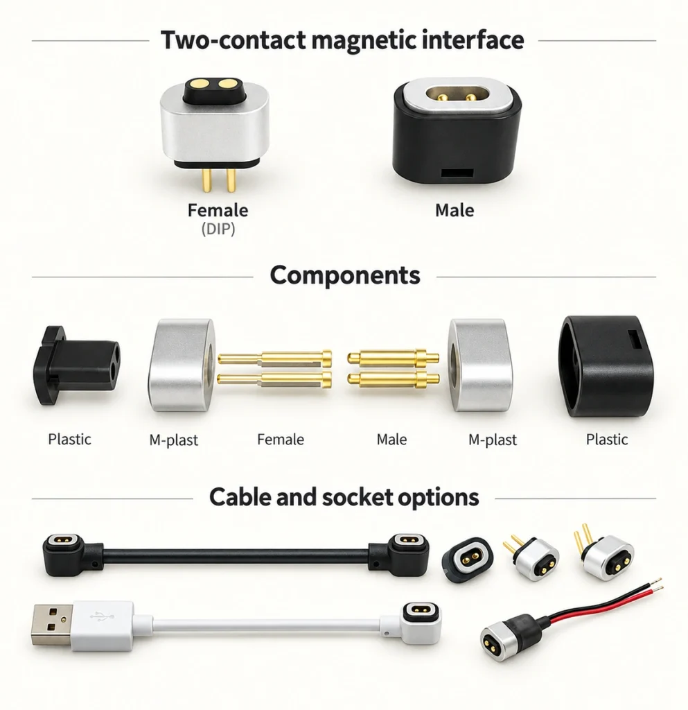
The magnets assist positioning and retention; they are separate from the current path. A common arrangement uses spring contacts on one half and plated pads on the other, although the male/female designation and exact structure depend on the mating drawings.
The assembly can include:
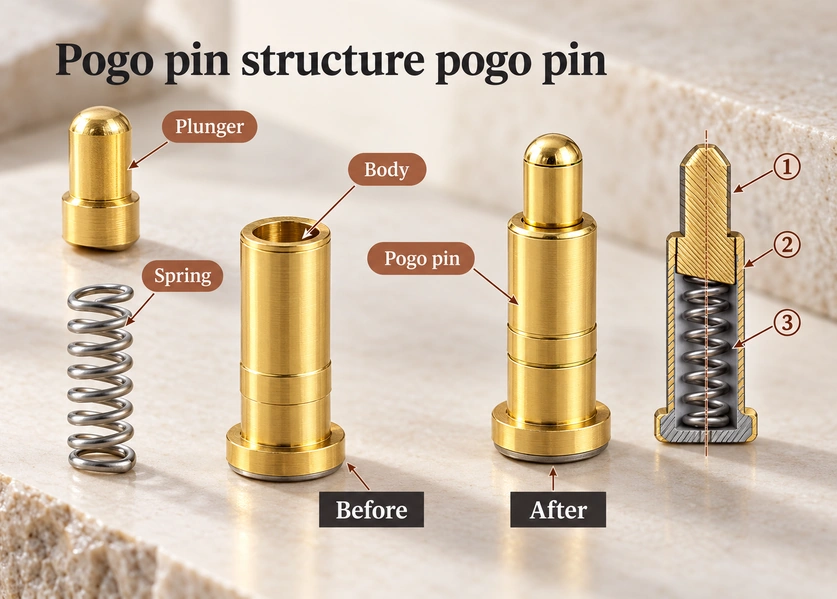
Spring contacts: Provide compliant electrical contact within their working travel.
Copper mating posts: Provide a conductive mating surface; they need not be spring-loaded.
Magnets: Assist engagement and retention.
Insulating housing: Locates the magnets and contacts and provides the required insulation.
Wire or PCB termination: Connects the interface to the circuit.
For outdoor or ingress-protected use, consider O-rings, adhesive seals, overmoulding or a sealed housing as appropriate. Their effectiveness depends on the complete installation and exposure tests.
Develop the structure from the available space, mounting, cable exit, ingress requirement and expected connection frequency.
Choosing power contacts
Review working voltage, continuous and peak current, resistance, contact dimensions and installation space. Electrical spacing and insulation must also suit the voltage and environment.
For a charging-power-only application, two contacts may suffice, for example:
two-contact magnetic connectorExample: Pin 1 = V+; Pin 2 = GND. Confirm the mating views and polarity.

A higher-current arrangement can use parallel contacts, such as two positive and two return contacts in a four-pin design. Validate sharing, return capacity and partial engagement instead of multiplying a single-contact rating by the pin count.
spring contactsParallel paths may reduce the load on each contact and help control drop and heating, but only when their impedances and actual engagement provide acceptable sharing.
Check:
Rated continuous current
Peak current
Initial contact resistance
Contact resistance after cycling
Spring force
Plunger diameter
Working stroke
Pin pitch
Gold plating specification
At higher current, even a small contact resistance can create significant resistive loss. Measure drop and temperature rise under the intended load and cooling conditions.
A mixed layout can use larger power contacts and smaller contacts for data, control, identification or sensing. Allocate each function and its return path; the contact size alone does not establish a protocol or data rate.
Magnet layout and polarity protection
Provide enough attraction for engagement and retention. Mechanical stops and the tolerance stack must keep every spring contact within its permitted compression, rather than relying on magnet force alone.
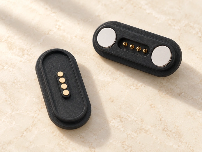
Examples include a magnet on each side of a contact row, a ring around a circular interface or several magnets around the housing. The electrical layout still determines permitted mating orientations.
The following image illustrates one arrangement:
Balance the force requirements against the connector size, cable weight, combined spring reaction and user handling. Too little retention can allow separation; excessive pull-off force can make removal difficult or increase stress. Define the actual release directions.
Check reversed engagement as well.
If a two-contact pair can still engage after a 180° rotation, its V+ and GND paths may be reversed. Possible controls include:
Asymmetric housing geometry
Unequal magnet positions
Magnetic polarity keying
Offset pogo pin layouts
Electronic reverse-polarity protection
Where reverse polarity could damage the circuit, mechanical keying and an appropriate electrical protection stage can reduce the risk. Validate both for the intended mating conditions.
Production controls should maintain magnet position and polarity, because variation can change alignment, attraction and contact compression.
Housing geometry and working height
The housing locates contacts, magnets, mating surfaces, PCB and cable. Its geometry defines alignment, support and the assembled tolerance relationships.
PCBSpecify these geometric relationships:
Pitch: The specified spacing between neighbouring contacts.
Working height: Contact height at the intended seated compression, relative to the drawing’s datum.
Magnet position: The arrangement and separation that establish guidance and attraction.
Mechanical stop: Limits compression so contacts stay within their permitted travel.
Insulation spacing: Selected for voltage, materials and contamination conditions to limit adjacent-contact faults.
At full engagement and tolerance extremes, each spring contact must remain in its recommended working range.
The intended sequence is:
Magnetic approach → controlled alignment → permitted spring compression → required contact pressure
Under-compression can cause interruption during vibration or tolerance variation. Over-compression can damage the spring or shorten life. Check minimum and maximum assembled compression against the actual contact specification.
Housing processes can include injection moulding, insert moulding, overmoulding or machining. Select the process from material, geometry, quantity and application requirements.
Possible termination and mounting options include:
- SMT
Through-hole electrical termination (THT)
Wire soldering
Screw mounting
Snap-fit
In-mold assembly
For a custom product, coordinate the housing with PCBA position, wall thickness, working height and installation envelope. Compare a standard part where it fits; otherwise develop the interface around those constraints.
Power-path protection
Quick or angled engagement can make individual contacts at different times, including temporary partial contact. Review those transients as part of the circuit and mechanical design.
Potential risks include:
Inrush current
Contact bounce
Short circuits
Reverse polarity
Voltage spikes
Electrical arcing
Select protection from voltage, current, battery behaviour and downstream circuitry, including the relevant fault and live-connection conditions.
An illustrative power-path review is:
Power source → fuse or eFuse functions → polarity protection and current control → magnetic interface → device charging or power circuit
For a low-power 5 V design, short-circuit and reverse-polarity protection are starting considerations, not proof that no other protection is needed. Review inrush, battery backfeed, load behaviour and live connection too.
For higher-current designs, assess limiting, soft start, thermal and overvoltage protection, and hot-plug behaviour. Lower-current circuits can also need those functions. An eFuse may integrate several functions rather than requiring one separate device per stage.
Contact heights and positions can establish a desired sequence, such as ground before a sensitive signal, or reduce temporary cross-contact risk. Confirm the make and break sequence over permitted angles and tolerances, together with the circuit response.
Review the magnetic contact assembly as part of the entire power path and its protection scheme.
Validation before production
A prototype powering a device once demonstrates basic operation, not production readiness.
Plan electrical, mechanical, environmental and life tests with stated acceptance criteria.
Electrical checks include:
Rated current test
Voltage drop
Contact resistance
Temperature rise
Insulation resistance
Short-circuit behavior
Mechanical checks include:
Magnetic attraction force
Separation force
Pogo pin spring force
Working stroke
Alignment tolerance
Cable pull force
Angled mating behavior
Cycle the representative pair while monitoring spring behaviour, finish wear and resistance. Thousands of test cycles only become a meaningful result with defined working height, load, environment and failure criteria.

For demanding exposure, consider:
High and low temperature
Temperature cycling
Humidity
Salt spray
Sweat resistance
Dust exposure
Vibration
Waterproof testing
Ingress testing must cover the relevant connector assembly and installed enclosure. Housing joints, seals, manufacturing controls and the mating state contribute to the result; testing a pogo pin alone does not establish protection.
Before tooling and release, confirm the electrical requirements, force behaviour, dimensional tolerances, mating-life target and environmental limits on representative assemblies.
Develop the interface in sequence: define voltage and current, choose the contacts, establish magnet layout and polarity controls, set working height, design electrical protection and complete the agreed validation. Magnets and conductors alone do not establish a reliable product.
Frequently asked questions
How should the contact count be selected?
Choose the number from the required electrical functions. Two contacts may serve positive power and return; additional contacts can serve ground, signals, identification or control. Parallel power contacts require validated sharing and return capacity, not a simple multiplication of their ratings.
What determines high-current capability?
Yes, with appropriately sized contacts and conductors or validated parallel paths. A mixed layout can reserve smaller contacts for signals. Establish the usable current from resistance, voltage-drop and thermal measurements in the intended assembly.
Can the power interface be ingress protected?
A sealed housing, O-ring, adhesive interface, insert moulding or overmoulding can form part of an ingress-protected design. Test the actual assembled interface and device under the declared IP conditions.
How should service life be validated?
Life depends on spring structure, plating, working travel, load, contamination and mating conditions. A defined cycling test should track resistance and mechanical performance against the application’s acceptance limits.
What inputs support a custom power-interface design?
Provide voltage and current, power and signal contact functions, dimensions, PCBA position, working height, retention and release targets, mounting, ingress conditions, cable exit, mating-life target and operating exposure.