
6-Pin Magnetic Connectors vs RJ12: Choosing for the Device
Published on August 17, 2026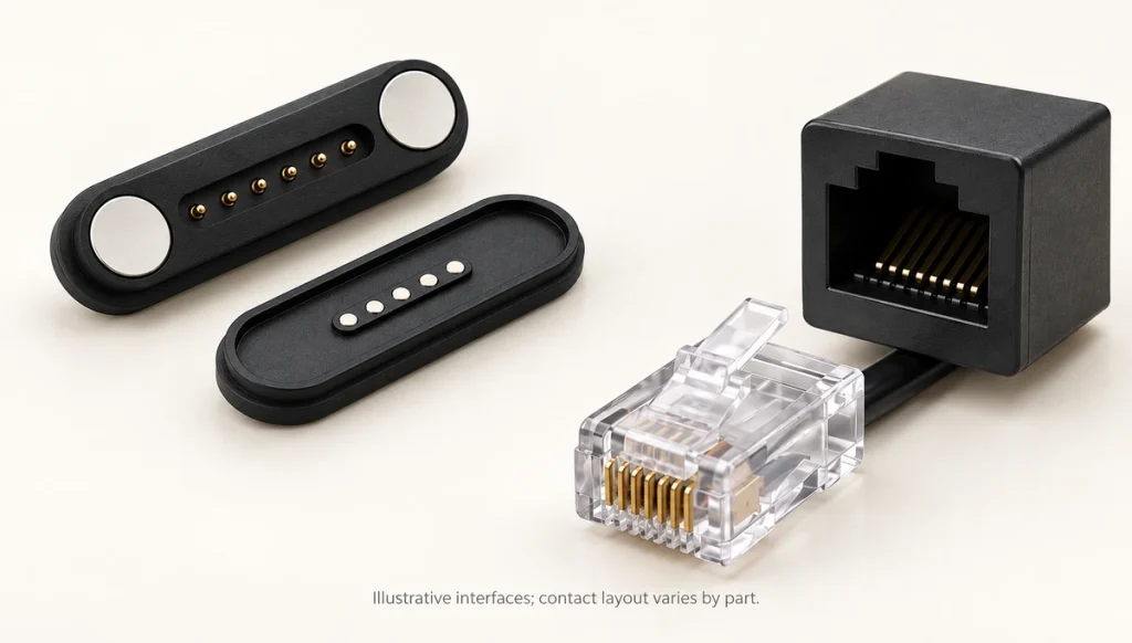
- Mating mechanism and integration
- Frequent charging and docking
- Power and signal requirements
- Space and mounting constraints
- Reasons to retain an RJ12 interface
- Reasons to consider magnetic contacts
- Making the interface choice
A six-contact magnetic assembly and a 6P6C modular interface can both provide six electrical paths, yet their mating actions and integration needs differ. Magnetic guidance suits a dedicated docking layout, while RJ12-style equipment uses a modular plug and jack. Compare attachment, electrical functions, enclosure space, cost and customization before choosing either.
six-contact magnetic assemblyRJ12Mating mechanism and integration
Start with the mating action and the space needed to install and operate it.
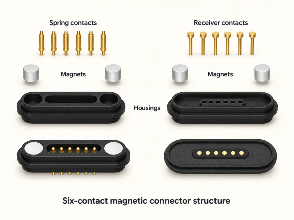
A magnetic six-contact pair combines spring contacts or matching pads with magnets. Within the designed capture range, attraction guides the halves together; the housing controls final alignment and contact compression.
An RJ12-style modular plug is inserted into a matching jack and commonly retained by a plastic latch. Its usual 6P6C construction means six positions with six contacts. Confirm the equipment wiring separately from the connector form.
six-position, six-contact modular construction| Selection factor | Six-contact magnetic assembly | RJ12 |
|---|---|---|
| Electrical contacts | 6 | Commonly 6 |
| Connection method | Guided magnetic mating | Inserted modular plug with latch |
| Alignment | Magnetic guidance and housing alignment | Manual plug placement |
| Mechanical retention | Magnetic force | Plastic locking tab |
| Pin assignment | Can be tailored to the product | Set by the equipment wiring |
| Housing dimensions | Can be developed for the enclosure | Standard modular format |
| Frequent docking | Suitable when life and retention requirements are validated | Requires repeated plug insertion and latch operation |
| Power transmission | Possible within the designed electrical and thermal limits | Possible within the chosen assembly and application ratings |
| Signal transmission | Possible with suitable pinout and signal design | Possible within the intended communication system |
| Device integration | Dedicated integration into the product | Defined modular mating format |
| Cable design | Cable configuration can be tailored | Modular cable options are available; verify wiring compatibility |
| Relative cost tendency | May be higher for a dedicated custom assembly | May be lower where a standard assembly meets the requirement |
Scroll horizontally to view every column.
A matching contact count is only one input. Mechanical, electrical and system compatibility still determine the appropriate choice.
Frequent charging and docking
Consider magnetic engagement where the product is connected and removed frequently, then validate the required mating life and handling action.
Guided attachment can reduce the effort of locating and inserting a plug. That can be useful for daily charging or repeated docking, provided the capture range, retention and contact travel suit the product.
Possible applications include:
Wearable products
Medical devices and equipment
Charging cradles
Handheld electronic devices
Connected home products
Portable industrial devices
A modular interface may suit a cable intended to remain attached for longer periods. Repeated use still involves plug insertion, removal and latch operation; check its specified mating life rather than assuming it cannot support frequent use.
A magnetic joint may separate under an accidental cable pull and reduce enclosure loading. Validate the release force, pull direction and device support; release is not a guarantee against damage or movement.
Power and signal requirements
Either interface can carry electrical signals within its design limits. A dedicated magnetic pair offers freedom to allocate six contacts around the device’s power, returns, detection and communication needs.
Example allocations include:
2 power + 2 ground + 2 signal
1 power + 1 ground + 4 signal
Power, return, data and identification functions
Charging paths with communication and control signals
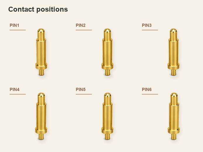
Choose the allocation from the required current paths, circuit functions, signal characteristics and PCB layout.
printed circuit boardOne dedicated interface can combine power and signals where the contact arrangement and electronics support both.
RJ12-style assemblies also contain multiple conductors. Their capability depends on the cable, contacts, wiring, voltage, current and intended communication system. They are often selected because the equipment already follows a modular connector architecture.
For both options, verify the electrical limits and required protocol. Six contacts alone establish neither an allowable current nor a data capability.
Space and mounting constraints
A custom magnetic assembly can offer more freedom to fit the product’s available mechanical envelope.
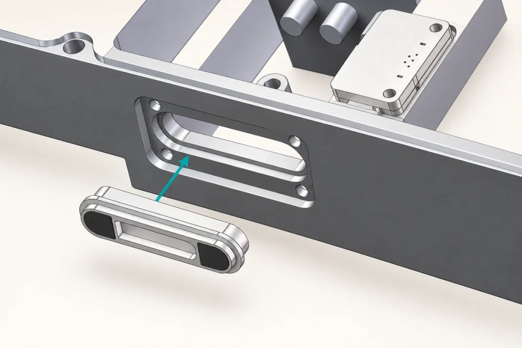
Reserve space for the modular jack body, plug-insertion path, latch operation and cable exit when integrating RJ12-style equipment.
Those operating clearances can be challenging in a small enclosure.
Inputs for a dedicated magnetic contact pair include:
PCB mounting position
Enclosure wall thickness
Available connector width and length
Required working height
Spring-contact working travel
Magnetic retention target
Cable exit direction
Mating orientation
Where the PCBA and enclosure are already defined, a magnetic assembly can be evaluated against the remaining installation space. The final design must still meet contact travel, strength, manufacturing and electrical constraints; it does not guarantee that no enclosure change will be needed.
That approach can suit wearables, compact medical products, smart devices and dedicated industrial equipment. The application label does not establish regulatory approval.
medical equipment applicationsReasons to retain an RJ12 interface
A modular interface is worth retaining where a standard mating form, available replacements and cost take priority over a custom docking action.
Consider RJ12 or a matching 6P6C interface when:
The equipment already incorporates a modular jack
Replaceable modular cables are needed, with the correct wiring verified
The cable normally remains connected
Magnetic guidance is not required
The enclosure has room for the jack and operating clearances
A suitable standard assembly meets the cost target
The product does not require a dedicated mating structure
The established modular format provides a range of plugs, jacks, cable assemblies and tooling. Verify that the selected parts and wiring match the equipment; general availability is not a stock or lead-time promise.
For an established modular system, changing the mating mechanism may add development work without a useful operational benefit.
Reasons to consider magnetic contacts
Evaluate a six-contact magnetic pair when the product needs a dedicated interface or repeated guided docking.
six-contact magnetic pairRelevant design priorities include:
Magnet-assisted positioning
Repeated charging and removal
A compact mating envelope
Product-specific contact assignments
Power and signal paths in one interface
Defined magnetic retention and removal effort
A working height tailored to the assembly
A suitable cable exit
Fit with the existing PCB and enclosure
A contact arrangement suited to the external product design
For an OEM product, the mating assembly can be developed around the device’s requirements rather than adopting a standard plug shape. Review feasibility and validation before finalizing that approach.
Project inputs can shape the contact assignment, dimensions, magnet polarity, working height, housing material, plating, retention, cable assembly and mounting. These features must work together within the mechanical and electrical constraints.
Making the interface choice
There is no single best interface for every application.
Choose a suitable modular assembly when established plug-and-jack integration, replacement-cable availability, cost and relatively infrequent removal meet the product’s requirements.
Consider magnetic contacts when guided docking, frequent charging, a compact envelope or dedicated pin functions justify a product-specific design.
For a new OEM product, begin with this decision:
Does the product need a standard modular cable connection or a dedicated docking interface?
Where modular compatibility is the priority, RJ12-style construction may be practical after the wiring and electrical requirements are confirmed.
Where custom power and signal paths, guided mating or compact repeated docking are central requirements, a magnetic six-contact pair offers a different integration route.
Selection summary
The important distinction is how the interface mates and fits the device, rather than the fact that both options can contain six contacts.
RJ12-style equipment uses an established modular plug-and-jack form. A dedicated magnetic pair allows the contact functions, dimensions, retention, working height and cable arrangement to be considered together for the product.
Compact electronics, charging cradles, medical devices and wearables are possible uses for that dedicated layout. Validate the specific configuration for its intended operation rather than treating the application category as proof of performance.