
Choosing Between Four- and Five-Contact Magnetic Cables
Published on September 14, 2026
- The Additional Electrical Path
- Example Contact Assignments
- Charging and Data Performance
- When Four Paths Are Enough
- When a Fifth Path Is Useful
- Choosing from Device Requirements
Four-contact cables offer four configurable paths; five-contact cables add one for ID, detection, control, data or another custom function. Neither count inherently raises speed or power. Choose according to the independent paths the device needs.
4 pin magnetic charging cableThe Additional Electrical Path
A four-contact assembly supplies four paths and a five-contact assembly five.
Their usefulness depends on the assigned functions.
Four paths might carry power and ground plus two data, detection or control functions. A fifth can add ID, another signal, detection, control or a different circuit function.
One four-contact example is:
Power + ground + signal 1 + signal 2.
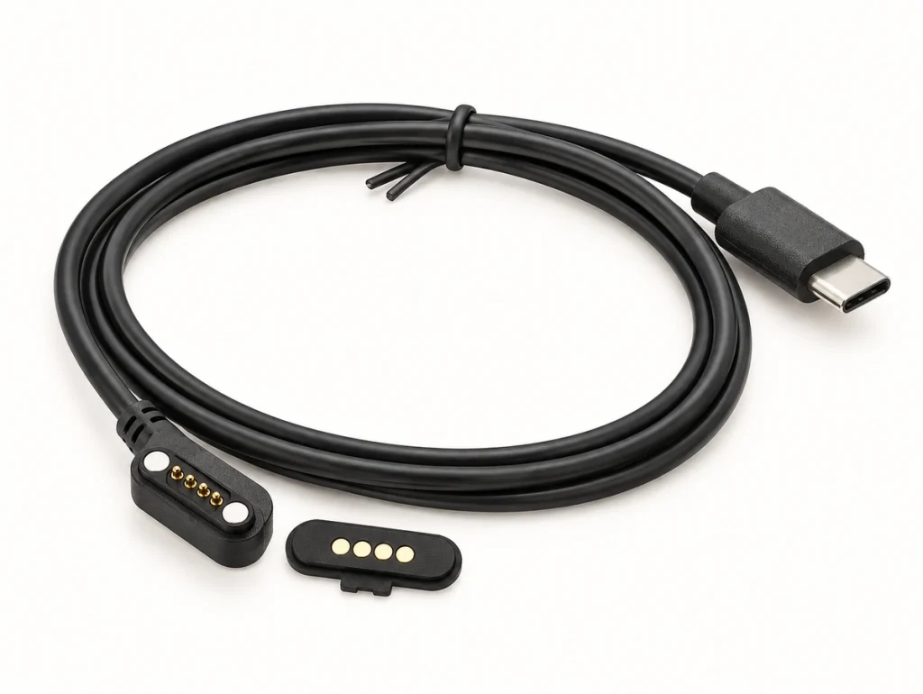
A five-contact version might add:
Power + ground + signal 1 + signal 2 + ID.
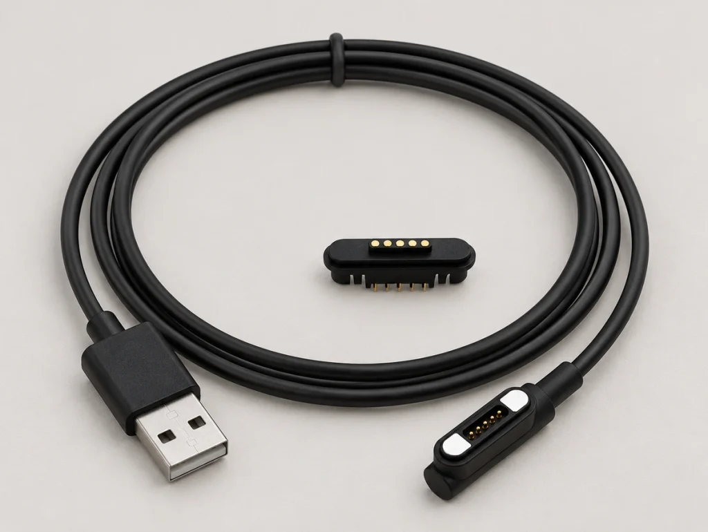
These are examples, not universal pinouts. Magtor four- and five-contact assemblies can have different maps according to the device circuit.
5 Pin Magnetic Charging CableExample Contact Assignments
Contact count gives available paths without defining their electrical roles.
Begin the comparison with the functions required by the device.
| Device Requirement | 4 Pin Example | 5 Pin Example |
|---|---|---|
| Power | V+ | V+ |
| Ground | GND | GND |
| Signal 1 | Data / Detect | Data / Detect |
| Signal 2 | Data / Control | Data / Control |
| Additional Function | — | ID / Detect / Control |
Scroll horizontally to view every column.
A four-path design may use VBUS, GND, D+ and D− for a suitable USB-style implementation, or V+, GND, ID and detection for another circuit.
A fifth path need not carry data. It may instead serve identification, charging detection, control or another project function.
Equal contact counts do not guarantee compatibility: assignments, polarity and the device circuit must match. The Magtor four-contact data guide explains why contact count alone does not establish communication.
MagtorCharging and Data Performance
Five contacts do not inherently charge faster or carry more power than four.
Charging depends on contact current limits, resistance, gauge, length, power-path allocation, PCB layout and thermal conditions.
For example, four contacts could be assigned to:
2 × power + 2 × ground.
That allocates more contacts to supply than this five-path example:
Power + ground + Data+ + Data− + ID.
The implication is:
Total count does not determine charging power. Parallel contacts need deliberate current-sharing and thermal validation.
A fifth path also does not determine data speed. Signal type, cable construction, wiring, PCB layout and communication electronics define that performance.
A Type-C plug at the source establishes no particular charging or data function through the magnetic head. Its supported functions depend on the complete implementation within the Type-C framework.
USB Type-CWhen Four Paths Are Enough
Consider four contacts when four independent paths satisfy the electrical requirements.
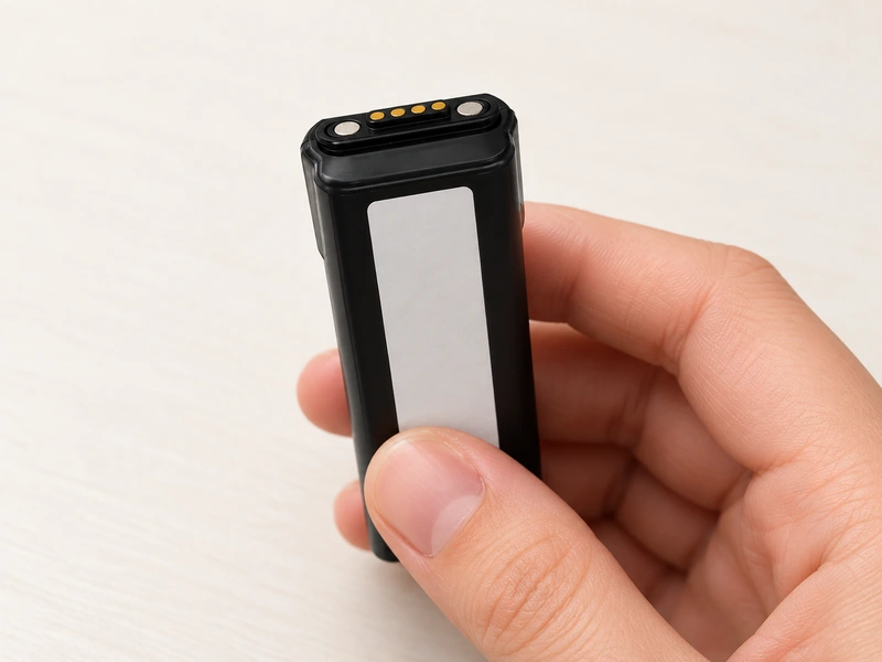
Power, ground and two data, detection or control paths may cover the needed functions. A fifth may then add no immediate function, though reserved needs should be assessed separately.
Two possible maps are:
Power + ground + Data+ + Data−.
Or:
Power + ground + ID + detection.
Four contacts may suit limited PCB space when no further independent signal is needed; actual size depends on the selected structure.
A broad comparison might ask:
Does a fifth contact improve this design?
The functional check is:
Can four contacts carry all required functions reliably?
If so, the four-contact layout may simplify the connector and wiring.
Magtor can develop four-contact assemblies with configurable maps and USB-A, USB-C, bare-wire or custom ends for the required power and signals.
When a Fifth Path Is Useful
Consider five contacts where an extra independent function is difficult to accommodate in four paths.
One possible arrangement is:
Power + ground + Data+ + Data− + ID.
Another is:
Power + ground + detection + control + ID.
The extra path provides allocation flexibility for charging with communication, accessory ID, status detection or control.
Examples include wearables, docks, medical electronics, handheld terminals and other products with a multifunction charging interface.
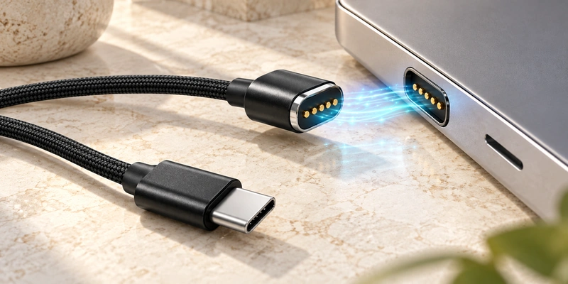
Give the fifth contact a defined purpose.
An unused contact can add wiring and PCB complexity without improving the product's required functions.
Use the fifth path to meet a real requirement. Magtor can assign it to ID, detection, control or another circuit-defined signal in a five-contact assembly.
Choosing from Device Requirements
Define functions first, then select count. The following comparisons show potential allocations that still require a matched electrical design.
| Design requirement | Four contacts | Five contacts |
|---|---|---|
| Basic power + ground | Possible | Possible |
| Two additional signal paths | Possible | Possible |
| Three additional signal paths | Needs more paths or a sharing architecture | Possible |
| Charging + detection | Possible | Possible |
| Charging + two signal lines | Possible | Possible |
| Charging + two signals + ID | Depends on path sharing | Possible |
| Custom assignment | Possible | Possible |
| USB-A or USB-C end | Possible | Possible |
| Automatically higher current | No | No |
| Automatically faster data | No | No |
Scroll horizontally to view every column.
Choose four where its paths cover the needed charging, data, detection or control functions.
Choose five where another independent ID, detection, control or signal path is required.
Before final selection, confirm the map, voltage, current, signals, pitch, dimensions, electrical polarity, magnetic polarity, outlet direction and device PCB layout.
For OEM work, these requirements provide a better basis for verification than appearance or count alone.
Select for the Required Paths
The extra contact matters when the device needs an additional independent electrical path.
Four paths may cover power, ground and two signals. Five adds a configurable path for ID, detection, control or another device function.
Neither count guarantees greater speed, power or suitability.
Let the required electrical functions determine the count.
Questions About Four and Five Contacts
What distinguishes four-contact and five-contact cables?
Their available paths: four configurable contacts versus five, with the extra path available for data, ID, detection, control or another device-defined function.
Does five-contact charging operate faster?
Not by count alone. Rating, resistance, gauge, length, PCB design and contacts allocated to power determine charging performance.
Can either count support data?
Yes, when assignments, wiring, device circuitry and the communication system implement it. Neither count independently proves data support.
When is a four-contact assembly appropriate?
When four paths meet the requirements, such as power and ground plus two signal, detection or control contacts.
When is a fifth contact needed?
When the design needs another independent function, for example supply, ground, two data paths and a separate ID or detection contact.