
Three-contact Magnetic Interfaces for Modular Electronic Keyboards
Published on July 3, 2026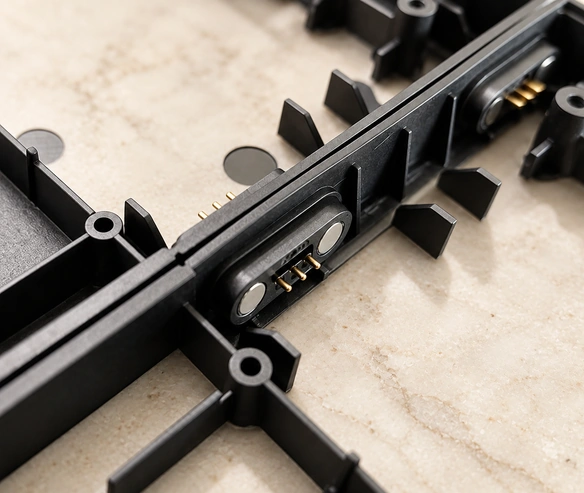
- The Three-contact Magnetic Interface
- Connecting Modular Keyboard Blocks
- Potential Benefits for Educational Keyboards
- Keyboard Interface Design Requirements
- When a Custom Design Is Useful
A modular educational keyboard needs blocks that are easy to join and electrically compatible. A three-contact magnetic interface can guide attachment and connect the assigned power and signal paths. This guide explains the integration concept and its potential benefits, while keeping child-product safety and electrical reliability subject to the complete product’s design and qualification.
Three-contact magnetic connectorThe Three-contact Magnetic Interface
The assembly combines magnets, locating structure and three conductive contacts, often using spring-loaded pins. A possible allocation is supply, return and a signal path. The magnets guide and retain the mating halves while spring compression establishes contact pressure; the actual functions follow the verified pinout and circuit design.
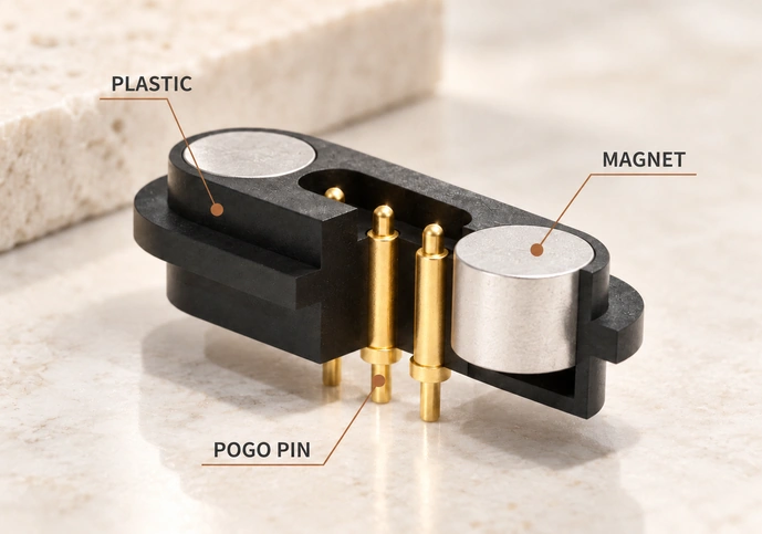
Functions that may be implemented include:
Power distribution.
A compatible signal-communication path.
Identification or synchronization through the assigned circuit.
Magnetic guidance can make joining modules intuitive, but the connection still has electrical, alignment and force requirements. It is not inherently safer than every insertion connector.
Connecting Modular Keyboard Blocks
In the example learning system, each key block is an independent module. A beginner can use a single block or combine blocks into a larger keyboard arrangement, provided the system supports the corresponding electrical and software functions.
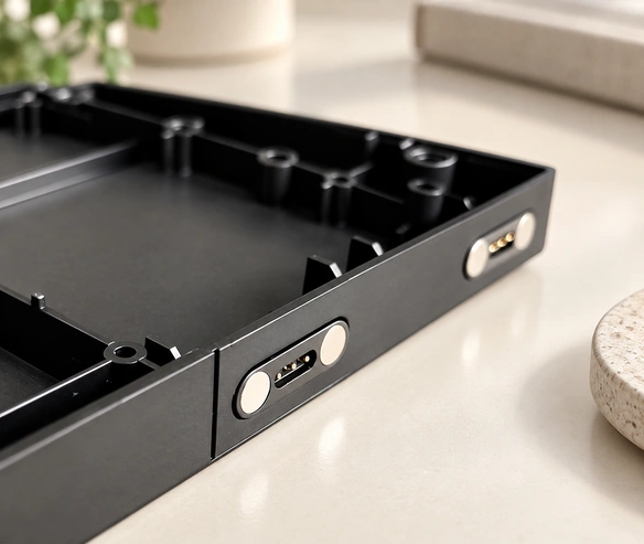
A purpose-designed three-contact interface sits at the side of each module. When two compatible blocks join:
The magnetic and mechanical geometry guide alignment.
The pogo contacts establish their assigned electrical paths.
Power and supported communication pass between the blocks.
The system control allows the connected modules to function as one keyboard.
This architecture allows a supported keyboard to expand gradually, with interaction and learning functions defined by the complete product rather than the connector alone.
Potential Benefits for Educational Keyboards

1. Straightforward Module Assembly
Small insertion connectors can be difficult to align. Magnetic guidance offers another approach for joining learning blocks, with the actual orientation and approach range defined by the product.
Conventional connectorsPotential handling benefits include:
Less insertion-direction effort when orientation control is designed correctly.
Quick connection of compatible modules.
A simpler assembly procedure to learn.
An interaction suited to young learners, subject to usability evaluation.
Guided attachment can make assembly intuitive. Verify that the intended users can connect and separate modules without incorrect engagement or excessive force.
2. A Designed Safety Arrangement
Children’s educational equipment needs a safety review of the complete product, including its connector and magnet retention.
Features to evaluate include:
Contact geometry that avoids inappropriate sharp exposure.
Controlled release at the specified force and direction.
A design that limits damage from forced insertion.
Wear performance appropriate to repeated assembly.
A validated breakaway arrangement may limit pull-related loads, but it does not by itself establish protection against accidental injury or product damage.
3. Power and Supported Signals
Electrical reliability depends on the allocated paths, contact system and control circuitry even when the user connection feels simple.
A suitable design may provide:
The required low-voltage power supply.
A supported keyboard-communication path.
The implemented synchronization function.
Contact resistance within the specified limits.
A suitable gold-plating system can support contact stability through thousands of mating cycles. Confirm the specific contact’s life test, signal performance and exposure requirements.
4. Modular Expansion
The connector can support a scalable arrangement when the electrical and software architecture permits additional modules.
The system may let users:
Start with one practice block.
Add further keys.
Arrange compatible blocks into a selected layout.
Build toward a complete electronic-keyboard experience.
Gradual expansion can give the product design flexibility and spread the user’s initial purchase across modules. Actual cost and learning benefits depend on the complete system.
5. Repeated-assembly Life
Educational modules may be handled and joined frequently, so the contact arrangement needs a suitable life target.
Requirements to specify and verify include:
Tens of thousands of mating cycles where required and validated.
Contact coatings suited to mating wear.
Appropriate magnetic holding force.
Electrical performance maintained through the defined test life.
A design that meets these requirements can reduce faults and servicing, but cost savings and product lifetime need actual evidence.
6. Compact Learning Modules
Portable keyboard blocks need an interface that fits their size and mass constraints.
A compact three-contact arrangement may provide:
A small mounting footprint.
A low-profile contact structure.
Limited internal assembly-space use.
Options for enclosure integration.
Evaluate those options when developing thinner or lighter modules with the intended appearance and structural support.
Keyboard Interface Design Requirements
Define the following requirements before selecting or customizing the interface:
Electrical Requirements
Current capacity for the connected-module load.
Allowed contact resistance.
Signal-integrity requirements.
Mechanical Requirements
Holding and release force.
Mating alignment and tolerances.
Required mating life.
Safety Requirements
Construction qualified for the intended children’s product.
Suitable protection against short circuits.
A release-force arrangement assessed in the complete product.
Environmental Requirements
Resistance to the relevant sweat exposure.
The specified corrosion requirements.
Dust protection appropriate to use.
A coordinated design and relevant qualification can support convenient handling and dependable operation; no single connector feature proves the whole product’s safety or reliability.
When a Custom Design Is Useful
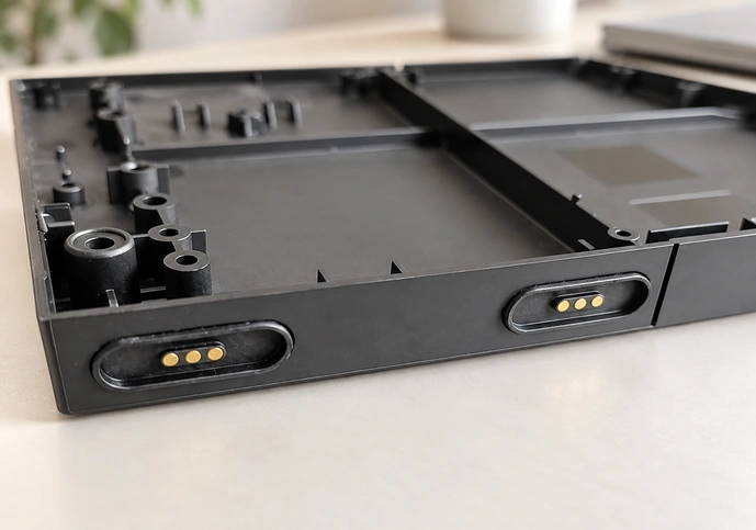
If a catalog part does not fit the module’s geometry or operating requirements, a custom interface may address:
magnetic connectorThe required magnetic holding and release force.
A contact layout matched to the circuit.
The module’s particular locating and mounting structure.
The specified mating-life target.
The intended user interaction.
A custom interface can contribute to a distinctive modular keyboard when the changes improve fit and are validated. Product quality and competitiveness depend on the complete design and production process.
Conclusion
The modular keyboard concept described by Magtor uses a three-contact magnetic arrangement to connect learning blocks. Magnetic guidance, spring-contact engagement and a compatible circuit can support quick module assembly and expansion. Define and validate the safety, electrical, mechanical and life requirements for the actual children’s educational product before relying on those benefits.
MagtorA suitably engineered spring-contact interface can support engaging modular interaction. User acceptance and safety must be evaluated for the product, rather than inferred from a general technology trend.