
Two-contact or Four-contact Magnetic Connector: Choosing the Functions
Published on July 21, 2026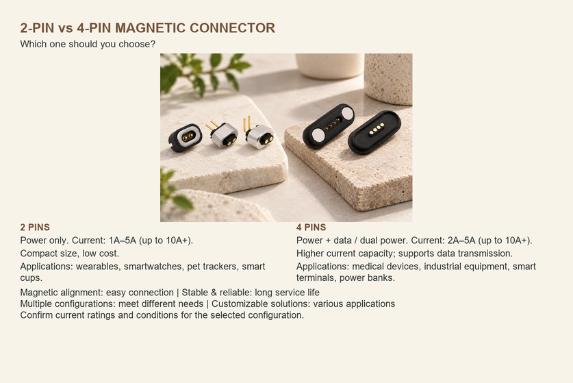
- Understanding a Two-contact Magnetic Interface
- Understanding a Four-contact Magnetic Interface
- Comparing Two and Four Contacts
- Benefits and Design Trade-offs
Two-contact magnetic designs commonly provide a compact supply-and-return connection. Four contacts add paths that can be assigned to data, control or separately designed power distribution, often with a larger envelope and higher cost. Start from the required electrical functions and compare actual assemblies rather than choosing by contact count alone.
Understanding a Two-contact Magnetic Interface
A two-contact magnetic assembly uses magnets and locating features to bring two conductive paths together. It is commonly used for compact charging interfaces and can simplify attachment within its capture range. Its release behavior, dimensions and cost depend on the design; safe disconnection under strain requires verification in the product.
2-pin magnetic connectors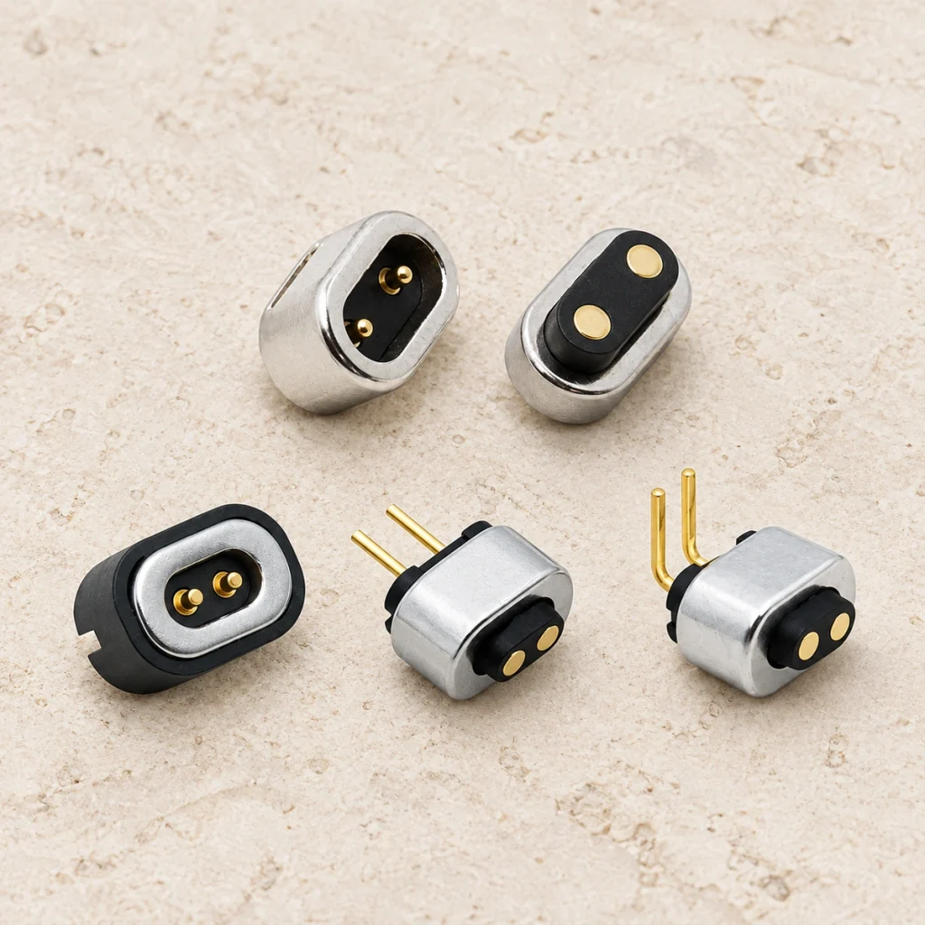
Typical function: a positive supply and return path, without separate dedicated data contacts in this arrangement.
Typical construction: two spring-loaded pogo contacts or conductive columns, with magnets providing guidance and retention.
Spring contactsCandidate applications: small wearables, miniature gadgets, lower-power docks and simple charging interfaces.
Expansion limit: there are no additional dedicated paths for data, identification or handshake functions. Carrying another function on the same paths requires a deliberately designed signaling or multiplexing system.
Understanding a Four-contact Magnetic Interface
A four-contact magnetic assembly provides four conductive paths that can be allocated to power and additional functions. Depending on the circuitry, those extra paths may support device detection, accessory identification, control or communication. More contacts often require additional space and manufacturing work, but compare the selected drawings and quotations.
4-pin magnetic connectors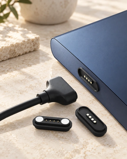
Possible functions: power plus data, control, identification, sensing or separately verified split power paths.
Typical construction: four spring contacts combined with magnetic guidance. Accurate docking also depends on the mechanical locating geometry and contact travel, not magnetic force alone.
Candidate applications: docks, communicating accessories, medical or industrial handheld devices, and products requiring a status or handshake connection.
Design trade-off: extra paths increase functional options while potentially adding bill-of-material cost, footprint and tolerance requirements.
Bill of materialsComparing Two and Four Contacts
| Comparison item | Two-contact magnetic design | Four-contact magnetic design |
|---|---|---|
| Contacts and possible functions | Two paths, commonly assigned to power | Four paths, allowing supported power, data, control or identification assignments |
| Size and footprint | Often compact for a constrained enclosure | May require more space for additional contacts and spacing |
| Cost | Often fewer parts and simpler assembly | May cost more because of the added contacts and tolerance requirements |
| Typical application | Basic charging in a small device | Smart docks, accessories and charging with supported communication |
Scroll horizontally to view every column.
Design guidance: consider four contacts when charging also requires identification, UART or I²C communication, status indication or accessory detection. Define the actual protocol and number of paths first. If future accessories or a smarter dock are planned, reserving sufficient contacts early may avoid a later interface redesign; it is not a rule that every additional function requires exactly four pins.
UART communicationI²C communicationBenefits and Design Trade-offs
| Design consideration | Two-contact arrangement | Four-contact arrangement |
|---|---|---|
| Compactness | Often an advantage in a restricted envelope | Often needs more space |
| Functional flexibility | Fewer independently assigned paths | More paths for supported signal functions |
| System cost | Often lower for a basic power interface | Often higher with extra contacts and functions |
| Design complexity | Usually simpler routing for power only | Additional routing, protocol and ESD design may be required |
| Typical fit | Small devices with a supply-and-return charging link | Power plus supported data or control for docks and advanced accessories |
Scroll horizontally to view every column.
Choosing the Arrangement
For a power-only charging link with tight size and cost constraints, a two-contact design may be sufficient. Where communication, identification, sensing or future functions need independent paths, a four-contact design may suit the requirement. Check the electrical allocation, physical envelope and cost of each candidate before deciding.
Common Questions
1. Is data possible over a two-contact magnetic interface? A common supply-and-return design has no separate data path. Communication over the power conductors is possible only with a specifically designed signaling system and compatible circuitry; assess the added complexity and reliability requirements.
2. How can the extra paths in a four-contact interface be used? Depending on the allocation and circuitry, they may carry UART, I²C or appropriate USB signal paths, accessory identification, charge status, enable signals, sensing or handshake functions. Four contacts alone do not establish protocol support or USB compliance.
USB signaling3. Should every product use four contacts? No. A two-contact assembly may be the better fit when only power is needed and reducing footprint and cost is a priority.
4. What can make a four-contact design more expensive? Added contacts can increase material and manufacturing work. Contact spacing, tighter tolerances and the associated electrical design may also affect the total cost; compare the actual assemblies rather than assuming a fixed price difference.