
A 2-Pin Pogo-Contact Charging Dock for Beauty Devices
Published on September 16, 2026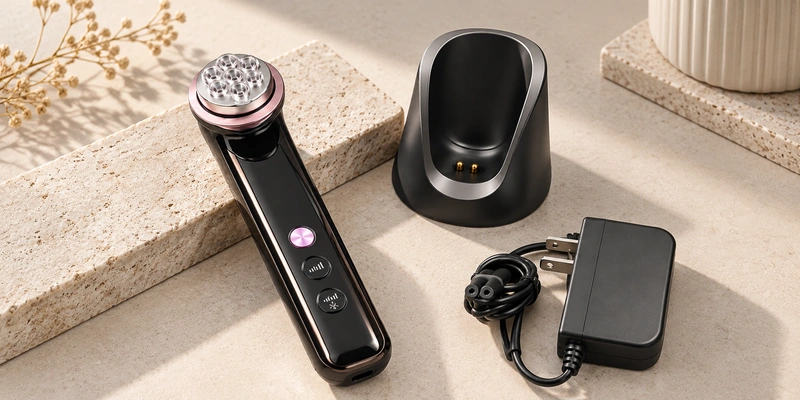
- Combining Storage and Charging
- How the Two-Contact Dock Works
- Selecting Two Power Contacts
- Setting Contact Force and Position
- Electrical and Mechanical Requirements
- Materials and Plating for Exposed Contacts
- Developing the Dock's Pogo Pin
- Design Lessons for Personal-Care Products
Magtor developed a two-contact pogo-pin charging interface for a beauty-device dock. The project specifies DC 9V/1.5A, a 0.90 mm working stroke, a 10,000-cycle mechanical-life requirement and a 96-hour salt-spray requirement for a compact, repeatable drop-in connection.
Combining Storage and Charging
Beauty and personal-care products may be returned to a countertop, dressing table or bathroom cabinet between uses. A dock can locate the device in a fixed resting position and provide its charging connection.
charging dockA stand can simplify the connection compared with inserting a cable into the handheld device after each use:
Place the device in the stand → align the charging area → pogo pins touch the device contacts → charging begins.
pogo pins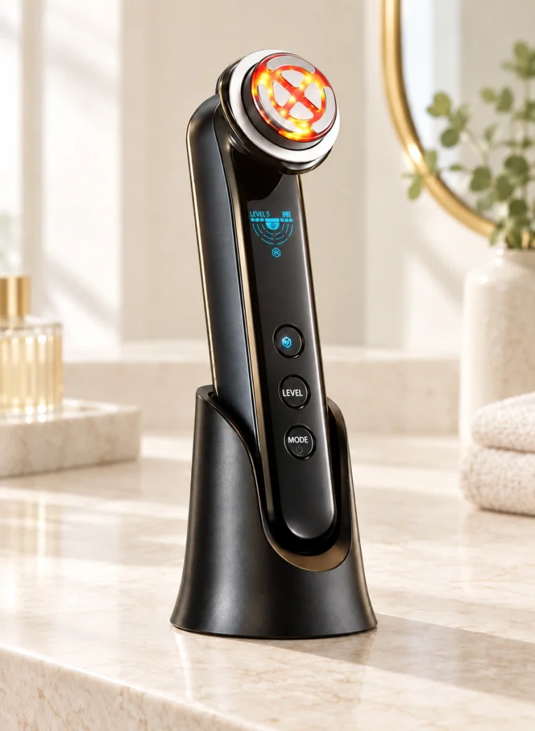
The dock can control the relative mating position. Reliable pogo-pin charging depends on the spring contacts, housing, device pads and mechanical guides working together as well as on the electrical specification.
Include the dock in the product's mechanical design before treating it as a final-stage accessory.
How the Two-Contact Dock Works
A two-contact dock typically places spring-loaded pins in the base. Seating the device compresses those pins against corresponding pads on the device.
spring-loaded contactsOne contact can carry positive power and the other the return path. In a charging-only interface, that arrangement avoids adding signal contacts that the system does not need.
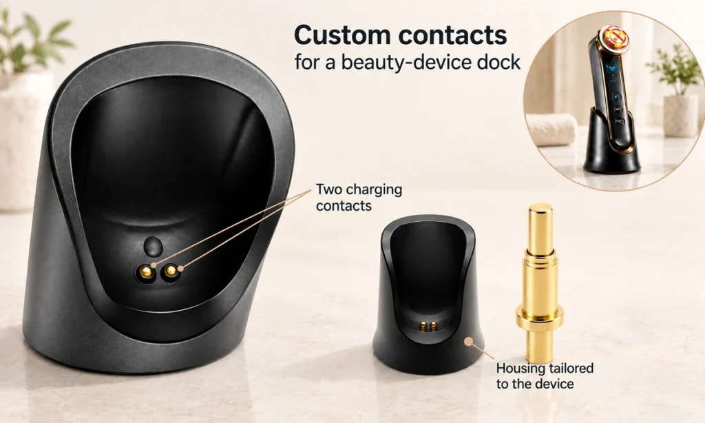
The project's pin has a 0.90 mm working stroke and a maximum mechanical stroke of 1.5 mm. It must operate at the designed working height without exceeding the permitted compression.
Spring travel permits a controlled amount of positional variation while keeping pressure on the pad. The user need not reproduce an identical sub-millimeter position each time, but the dock still needs adequate guidance and tolerance control.
Selecting Two Power Contacts
Two electrical contacts can provide the basic power path when the device needs only power from the base.
The project specifies the pogo pin at DC 9V / 1.5A.
Using the contacts required by the circuit can reduce interface space and simplify the base layout.
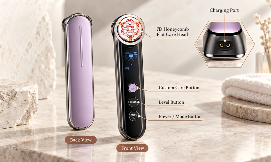
A basic system arrangement is:
Charging adapter → dock PCB → 2 pogo pins → device charging contacts → internal charging circuit.
Two contacts will not suit every beauty-device interface.
Device identification, communication, temperature sensing, charging detection or accessory recognition may require additional contact paths.
Choose contact count from the circuit's functions and architecture.
Setting Contact Force and Position
Contact force is a key input for a spring-contact dock.
When the device seats, the pins need sufficient compression to maintain contact with their pads. Too little compression can make the connection sensitive to movement and tolerances; too much can stress the pin and surrounding structure.
For each project pin, spring force is listed as 150g +50g at a 0.90 mm working stroke; maximum stroke is 1.5 mm. Confirm the force unit and the one-sided tolerance notation in the approved specification.
Design the dock so fully seating the device brings each pin to its intended working height.
The mechanical relationship is:
Dock position → pogo-pin compression → spring force → contact pressure → electrical connection.
Overall pin length alone is insufficient. Assess working height, stroke, spring force, pad position and mechanical tolerances together.
Electrical and Mechanical Requirements
Frequent placement and removal can demand both mechanical durability and stable electrical contact.
The selected spring contact is specified for 10,000 mechanical cycles and a maximum contact resistance of 30 mΩ. Confirm the durability conditions and criteria for the selected configuration.
mechanical life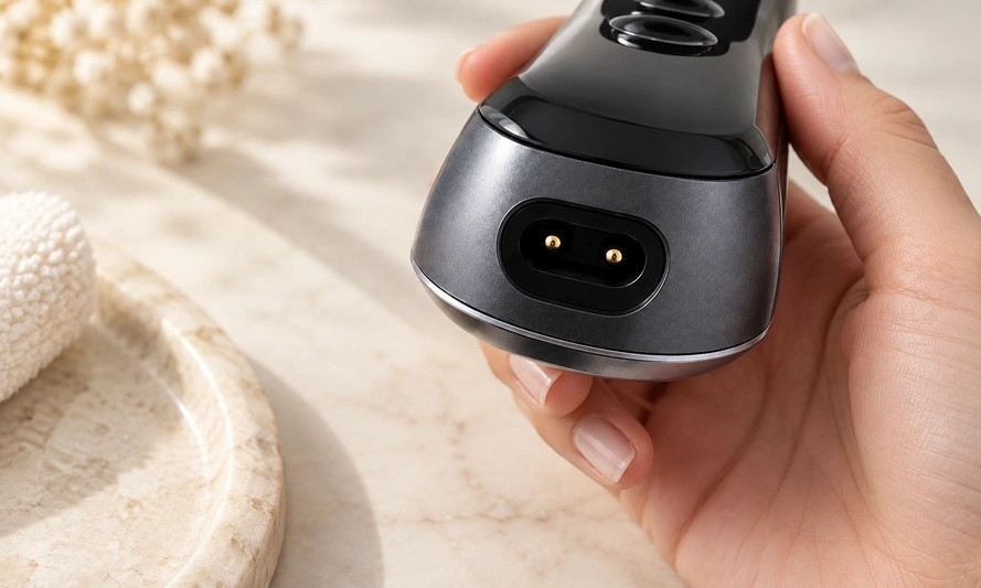
The dock needs acceptable contact quality after repeated pin compression; the listed values define requirements for that assessment.
The project specification includes this electrical recommendation:
For operation above 1A, a 3-second delay circuit is recommended.
Treat that delay recommendation as part of this project's design. It is not a universal rule for all pogo-pin charging interfaces.
During OEM development, evaluate the contact specification with the charging circuit and its operating sequence.
Materials and Plating for Exposed Contacts
Exposed personal-care charging contacts may encounter harsher conditions than connections inside a sealed enclosure.
Moisture, skin oils, cosmetics, cleaning residues and other contamination can reach the charging area. Include the contact material and plating in the selection review.
The project lists lead-free HBi59 brass for both plunger and barrel, a 1.25–2.5 μm nickel underlayer, 0.25 μm gold plating and a SUS304 stainless-steel spring. Verify the stated material designation against the approved drawing.
gold platingThe specification also lists:
Operating temperature: -40°C to +105°C
Salt-spray test requirement: 96 hours
Solder-heat resistance requirement: 260°C ±5°C for 20s ±2s
These requirements help assess the contact beyond its current rating alone.
For personal-care projects with other moisture, corrosion or finish requirements, Magtor can assess alternative plating structures against the intended environment.
Developing the Dock's Pogo Pin
This charging contact was developed around the base's mechanical position and electrical requirements.
The project describes a compact vertical pin with approximately 9.80 mm overall length, 8.90 mm normal working height, Ø2.00 mm plunger diameter, Ø3.00 mm barrel diameter and Ø4.00 mm lower flange diameter.
The pin must fit the PCB and housing while placing its tip correctly relative to the device's charging pads.
Key design inputs are:
Available installation height → pin diameter → PCB position → working height → spring force → current rating → pad spacing → housing guidance.
A dock contact is normally selected or developed for the actual device structure, with current rating forming one part of that review.
Project Pogo-Pin Specifications and Requirements
| Project Item | Listed Specification or Requirement |
|---|---|
| Application | Beauty-device charging dock |
| Contact configuration | 2 pogo pins |
| Rated voltage/current | DC 9V / 1.5A |
| Working stroke | 0.90 mm |
| Maximum stroke | 1.5 mm |
| Spring force at working stroke | 150g +50g at 0.90 mm |
| Maximum contact resistance | ≤30 mΩ |
| Mechanical-life requirement | 10,000 cycles |
| Operating temperature | -40°C to +105°C |
| Salt-spray test requirement | 96 hours |
| Plunger material | Lead-free HBi59 brass |
| Barrel material | Lead-free HBi59 brass |
| Gold plating | 0.25 μm Au |
| Nickel underlayer | 1.25–2.5 μm Ni |
| Spring material | SUS304 |
| Working height | 8.90 mm |
Scroll horizontally to view every column.
Design Lessons for Personal-Care Products
Two metal contacts and a stand require a coordinated charging-interface design.
Reliable contact depends on device housing, pad position, working height, spring force, current requirement, PCB position and the base's mechanical guidance working together.
For a charging-only product, two pogo pins can form a compact interface. Additional functions may call for more contacts and a different circuit architecture.
The same design method can be considered for:
Facial beauty devices, cleansing devices, electric shavers, hair-removal devices, handheld wellness products and other rechargeable personal-care electronics.
For OEM projects, Magtor can develop a spring contact using the device drawing, PCB position, charging voltage and current, working height, spring force, plating and environmental requirements.
Designing the Complete Dock Interface
A two-contact pogo-pin dock can combine storage and charging for a handheld beauty device.
In this application, Magtor developed contacts specified at DC 9V / 1.5A, with 0.90 mm working stroke, a 10,000-cycle mechanical-life requirement, 30 mΩ maximum contact resistance and a 96-hour salt-spray requirement.
Working height, stroke, spring force, PCB arrangement, pad position, current rating and plating all belong in the combined electrical and mechanical design of the charging interface.