
Four-pin Magnetic Connectors: A Design and Purchasing Guide
Published on May 21, 2026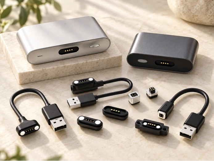
- What a Four-pin Magnetic Interface Contains
- How the Male and Female Halves Connect
- Benefits of Four-pin Pogo Contacts
- Maintaining a Four-pin Magnetic Connection
- Pricing a Four-pin Magnetic Connector
- Total Cost and Purchasing Considerations
- Conclusion
Four-contact magnetic interfaces use magnetic alignment to make a quick connection for power, signals or data, depending on the assigned circuits. Wearables, smart-home products, handheld equipment and medical devices are among the possible applications. This guide explains the structure and operating sequence, then covers benefits, selection and the checks needed before volume production.
What a Four-pin Magnetic Interface Contains
A four-pin magnetic connector combines four electrical contacts with magnets and a supporting housing, often made from plastic. The magnets guide and hold the mating faces; spring-loaded contacts establish the conductive paths. This face-contact arrangement can simplify blind mating and reduce some of the mechanical wear associated with repeated insertion into a conventional port.
Common Structures and Application Examples
The four conductive paths may be assigned to power, ground and two signal lines, but that is an example rather than a mandatory pinout. Magnetic force handles alignment and retention, while compressed spring contacts carry the electrical connection. The application determines what each contact actually does.
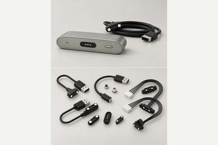
magnetic connectorCommon physical arrangements include the following:
Four-pin magnetic cable assembly — a device-side receptacle mates with a contact head on the cable. The opposite cable end may use USB or another specified interface for power or supported data functions.
Four-pin male/female connector pair — two mating assemblies provide a quick connection between a device and its dock, or between structures within a product.
Four separate magnetic pogo contacts — individual spring pins can mount directly in a space-constrained device without a shared plastic retainer, with magnets installed separately from the contacts.
Examples of where these arrangements may be considered:
Consumer electronics, wearables, medical sensors and smart-home devices that are connected and disconnected frequently.
POS terminals, handheld scanners and portable power banks using dock charging.
Point-of-sale tablets and industrial controllers requiring a quick removable interface.
Application note: select features for the equipment’s actual operating conditions. High-current capability, water protection and corrosion resistance can change the cost significantly; specify them where the application requires them rather than adding every available option.
MagtorHow the Male and Female Halves Connect
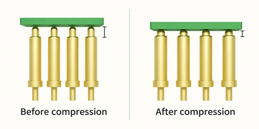
As the mating faces approach, magnets draw them into the intended position and the four contacts engage. Spring movement accommodates the specified tolerance, limited misalignment and vibration while maintaining contact force. Current or supported signals then pass through the contact paths; suitable plating helps control resistance and corrosion.
Alignment, Contact Force and the Electrical Path
A typical spring-contact design combines four functions:
Magnetic guidance and retention — the magnets draw the assembly into its seated position and reduce the risk of incomplete engagement.
Mechanical compliance — spring-pin compression accommodates the tolerance stack while providing contact pressure.
Conductive surface — gold plating is one common option for controlling contact resistance and improving corrosion resistance.
gold platingHousing geometry — locating and keying features help maintain repeatable alignment and avoid incorrect polarity.
The connection sequence can be described in five stages:
Approach — bring the cable head or docking half toward the receptacle.
Alignment — the magnetic arrangement guides the two mating faces into position.
Compression — the spring pins compress to establish the intended contact force.
Conduction — power or the assigned signals pass through the four circuits.
Release — an appropriate pull or lateral release separates the magnets without relying on a mechanical latch.
Performance depends on the complete contact and assembly design:
Current capacity is affected by pin dimensions, spring force, plating and the permitted temperature rise.
Signal performance depends on stable contact resistance, pin allocation and any required cable shielding.
Exposed contacts need a short-circuit and safety review, including pad recesses, spacing and suitable protective circuitry.
Mating note: dragging the halves sideways into engagement can bend or unevenly compress pins that were designed for another mating direction. In the damaged-contact scenario described here, life may fall to only a few thousand cycles; this is not a general rating for every lateral-contact design. At higher operating voltages, specify the necessary contact protection, insulation and personnel safeguards for the actual equipment.
Benefits of Four-pin Pogo Contacts
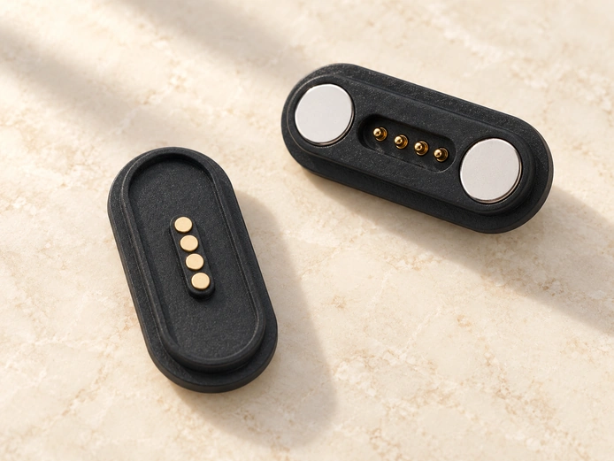
A suitably designed magnetic interface can make repeated docking easier by reducing the alignment and insertion effort. It may also limit damage from incorrect mating and reduce some friction-related wear. Spring compliance helps maintain electrical contact under the permitted vibration and small positioning differences, provided the application remains within the validated mechanical limits.
Advantages for Product Integration and Everyday Use
The practical benefits to evaluate include:
Ease of use — magnetic guidance can simplify alignment and provide a recognizable snap-in connection.
Mating life — suitable designs may target tens of thousands of cycles, and specialized designs may target hundreds of thousands; verify the particular assembly and test conditions.
Device protection — a designed breakaway response can reduce cable-pull damage.
Docking speed — quick attachment can support charging-station and cradle workflows.
Tolerance accommodation — spring travel can absorb the specified manufacturing and assembly tolerances.
Examples of how those benefits relate to applications:
Wearables — comfortable integration and quick charging attachment.
Medical equipment — reliable reconnection after the specified cleaning routine.
Industrial docks — rapid turnaround with validated vibration tolerance.
Retail and POS equipment — straightforward staff operation and fewer insertion-related port problems.
Life-cycle note: connection frequency and exposure differ between industries, so service life cannot be assumed from pin count alone. Review the required lifetime alongside connector size, plating, contact design and operating environment, then confirm the relevant mating-life evidence.
Maintaining a Four-pin Magnetic Connection
Keep the mating surfaces dry and free of contamination, particularly ferrous particles attracted by the magnets. Inspect pin movement, spring return and plating wear at an interval suited to use. Avoid solvents that damage plastics or seals, and follow the intended mating direction to limit side loading and uneven contact wear.
Checks for Stable Contact Resistance
A practical inspection routine is:
Power the equipment down before cleaning to reduce the risk of bridging live contacts.
Remove iron dust or other metal particles with a compatible nonmetallic tool or suitable tape; attracted debris can bridge adjacent pins.
Use lint-free swabs, with electronics-grade IPA only where the assembly materials and maintenance instructions allow it.
isopropyl alcohol (IPA)Check that every pogo pin moves freely and returns fully; sticking may indicate contamination or wear.
Look for pitting or discoloration that may indicate arcing, overload or moisture exposure.
Inspect cable strain relief, since a damaged conductor or relief can produce intermittent faults that resemble a contact problem.
Check seating, housing shape and mounting security; distortion or looseness can reduce contact force and increase resistance.
Typical symptoms and possible causes include:
Intermittent charging — contaminated pads, worn plating or a broken cable conductor.
Connector heating — increased contact resistance, excessive current or incomplete engagement.
Corrosion — sweat, salt or fog exposure beyond the protection provided by the plating and sealing.
Contamination note: magnetic debris can be difficult to notice when mixed with other residue around the contacts. Keeping the faces clean and preventing particles from entering the pins can reduce many intermittent-contact problems, but persistent faults still require inspection of the cable, contacts and seating.
Pricing a Four-pin Magnetic Connector
Price depends on rated current, plating, magnet grade, sealing, cable-assembly complexity and any required compliance evidence. The source discussion gives $1–$2 as an illustrative range for a simple four-pin magnetic cable connector; it is not a current offer and has no stated quantity or quotation conditions. High-reliability contacts and sealed device ends generally add cost, especially when high current, corrosion exposure or water protection must be validated.
four-pin magnetic connectorsPrice Drivers and Quotation Inputs
The major quotation variables are:
Supply format — a bare mating pair or a complete cable assembly.
Materials — gold-plating material and thickness, plastic material and color, and magnet dimensions.
Sealing — gaskets or a tested IP design can add parts, processes and cost.
IP-ratedElectrical load — higher current may require larger contacts and a revised thermal design.
Customization — housing geometry, keying, overmolding, logos and a special pin assignment.
For an informative pricing request:
Supply the pinout, current and voltage, mating-life target, sweat/salt/fog exposure, required IP protection, cable length, connector dimensions and expected annual quantity.
Quotation note: current rating, plating, mating cycles, IP protection and the real application all influence the final unit price. Detailed requirements let a manufacturer evaluate a matching design and provide a quotation with identifiable technical and commercial conditions.
Total Cost and Purchasing Considerations
The connector’s unit price is only part of the installed cost. Cable assembly, overmolding, sealing and production test yield can be substantial contributors. Match the electrical load, environment, mating life and mechanical limits to a suitable series, then test samples under representative engagement and contamination conditions before choosing the production configuration.
Purchasing Checks That Affect Cost
Review these requirements before ordering:
Electrical load — operating voltage, current per pin, peak current and inrush behavior.
Pin count — additional contacts can increase assembly complexity and cost; compare the actual configuration.
Exposure — sweat, salt fog, chemicals, metal dust and the specified cleaning process.
Mechanical limits — tolerance stack, docking angle, permissible side load and magnetic retention force.
Life-cycle target — mating cycles and acceptable change in contact resistance.
Manufacturing integration — SMT, through-hole or wire mounting, potting or overmolding needs, and production testing.
Possible cost controls include:
Use established footprints and available geometries where they meet the requirements.
Avoid unnecessary connector IP targets when the verified enclosure design already provides the required protection.
Choose plating material and thickness for the actual environment, then verify corrosion performance under relevant sweat or salt-spray conditions.
Sourcing note: ask whether an existing connector design serves a comparable industry and fits your requirements. Reusing suitable tooling can reduce the time and cost of a new plastic mold, while still requiring validation in your device.
Conclusion
Four-pin magnetic interfaces can provide quick, repeatable docking when the contact structure matches the current, exposure and mating-life target. Choose a suitable arrangement, specify the plating and sealing, and validate contamination and side-load behavior in the real assembly. A pogo-contact design may suit frequent docking, but its suitability depends on the model and test results.
Project discussion: share the current and voltage, pinout, operating environment and target mating life with Magtor. Those inputs support a connector shortlist and a validation plan for intermittent-contact risks before production ramp-up.