
How Magnetic Connectors Work and Where They Are Used
Published on April 27, 2026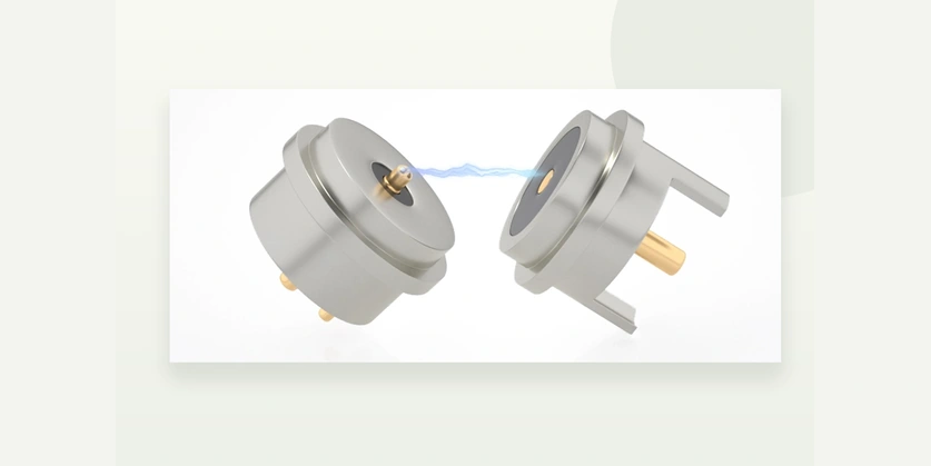
- Magnetic Alignment and Consistent Electrical Contact
- Comparing Magnetic, Plug-in, Latch and Threaded Connectors
- Blind Mating and Custom Connector Geometry
- Wear, Plating and Mating Life
- Applications Across Seven Industries
A magnetic connector uses magnets to guide and hold its mating halves, with pogo pins carrying power or signals. The arrangement makes alignment quick and precise. Spring-loaded pins maintain contact pressure, while gold plating supports low contact resistance and resistance to corrosion.
Magnetic connectorsMagnetic Alignment and Consistent Electrical Contact
As devices become lighter and more intelligent, magnetic interfaces provide a connection approach built around both magnetic alignment and electrical contact. The main parts are magnets, pogo pins and a plastic housing. Bringing the male and female halves together allows the magnets to position and retain the contacts accurately, creating the connection needed to transfer current and signals consistently.
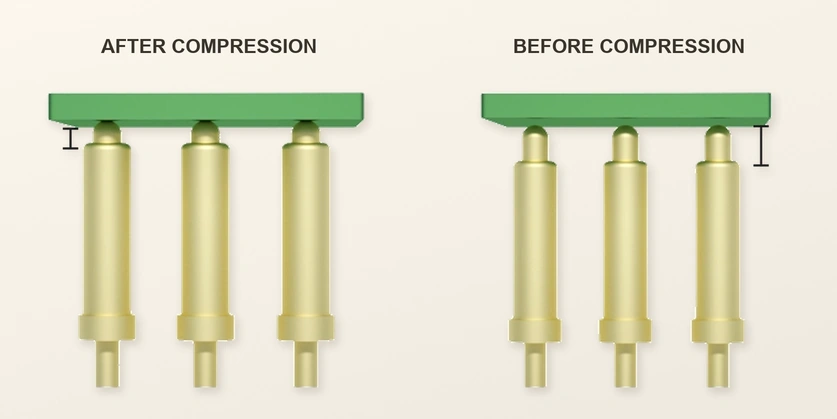
Compressing the internal spring supplies ongoing contact force. This helps keep contact resistance consistent when a device experiences small movements or minor vibration. Pogo pins commonly use gold or composite plating to combine electrical conductivity with protection against oxidation.
Comparing Magnetic, Plug-in, Latch and Threaded Connectors
| Comparison | Magnetic Connector | Standard Plug-in Connector | Latch-type Connector | Threaded Lock Connector |
|---|---|---|---|---|
| Mating method | Magnetic alignment for blind mating | Manual alignment followed by insertion | Insertion secured by a latch | Screw connection tightened in place |
| Connection and removal | Magnetic engagement requires little effort or manual alignment | Insertion takes force and accurate alignment | Operate the latch to connect or release | Threading takes more steps and the most time |
| Retention | Magnetic hold remains secure under a light pull | Loosening can cause an accidental separation | Latch retention is effective, though the latch can age | Strong retention suited to industrial use |
| Wear and service life | Low surface friction and wear can support long mating life | Repeated insertion wears contacts and can damage pins | The latch mechanism can develop fatigue | Threads can wear or strip |
| Water and dust protection | A fully sealed design can target IP65~IP68; verify the complete assembly | Large openings offer limited protection in the compared design | The compared design provides moderate sealing | The compared design provides strong sealing |
| Incorrect mating prevention | Magnetic polarity and keyed geometry guide correct mating | Reverse insertion can risk electrical damage in the compared design | Some mechanical guidance prevents incorrect mating | Fixed mating specifications reduce the risk of a wrong connection |
| Emergency separation | A forceful pull can release the magnetic joint and protect the device | A strong pull may damage the cable or port | A forceful pull can break the connector | A strong pull can tear the device port |
| Example applications | Wearables, small appliances, medical equipment and smart devices | Digital accessories and home appliances | Automotive, smart home and small devices | Industrial equipment and outdoor heavy machinery |
| Relative cost | Medium: magnets and housing structure | Low | Medium to low | High |
| Appearance and use | Minimal profile and close-fitting integration | Visible port with a conventional appearance | Protruding latch gives a less integrated appearance | Larger form with an industrial appearance |
Scroll horizontally to view every column.
Blind Mating and Custom Connector Geometry
Magnetic attraction and the mating geometry make blind mating possible: once the halves are close enough, they draw together without the user having to align them precisely. USB interfaces commonly need manual positioning before insertion. For a custom design, the pogo pin count can be selected to suit the circuit, and the plastic housing can be molded for the required structure. The source does not specify a universal magnetic engagement distance.
USB connectorsWear, Plating and Mating Life
Frequent docking makes wear at the interface an important consideration. Repeated USB insertion and removal rubs the contact surfaces; the source comparison cites a typical life of about 10,000 cycles. A magnetic interface instead makes a surface contact with little sliding friction at each connection, so its plating can wear more slowly. Gold, silver, nickel and composite coatings can combine conductivity and corrosion resistance with mating life in the tens of thousands, or even hundreds of thousands, of cycles. Those figures depend on the connector and its test conditions and are not a rating for every model.
Applications Across Seven Industries
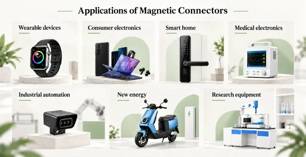
Smart wearables — Smartwatches, fitness trackers and Bluetooth headset charging ports use blind mating to simplify charging and reduce wear. A 2 pin magnetic connector is a common arrangement for supplying power.
2 pin magnetic connectorConsumer electronics — Tablet docks, magnetic phone charging cables, game controller docks and POS terminals benefit from quick connection, fitting and removal. Designs can carry both power and data to make everyday use easier.
Smart home — Lighting, door locks, motorized curtains, speakers and televisions can use magnetic connections to simplify installation and maintenance. A sealed design can resist water and dust and reduce the need to repeatedly undo screws.
Medical electronics — Portable medical devices, monitor interfaces and therapy-device charging ports need stable connections during frequent docking. Water and corrosion resistance, reliability and safe operation are design requirements for these applications.
Industrial automation — Controllers, robot interfaces and sensor connections may need resistance to vibration, reliable operation in difficult environments and higher current capacity. Magnetic holding force can be specified to suit the project.
New energy and electric equipment — Drones, industrial power tools and electric-vehicle auxiliary equipment are examples where easy fitting and removal must be combined with secure retention. The source describes current requirements of 1A–30A for this application group; the selected connector and operating conditions must be checked.
Education and research — Laboratory instruments, experimental teaching kits and removable electronic modules benefit from quick module changes and repeatable experiments. Simple mating also helps reduce the risk of damage during repeated handling.
Electrical and mechanical requirements change with the equipment and its industry. Wearables usually prioritize compact dimensions and corrosion resistance, while industrial equipment, drones and robots may call for higher current capacity. At Magtor, engineers discuss how the customer’s equipment will actually be used before developing a magnetic connector solution, so the chosen performance and structure can address the requirements of that device.
high current magnetic connectorsMagtor