
Selecting a Magnetic Power Connector for Your Product
Published on May 23, 2026
- Electrical, Mechanical and Environmental Selection Factors
- Turning Product Requirements into a Validated Connection
- Matching the Interface to Its Application
- Maintaining the Magnetic Contact System
- Wholesale Pricing, MOQ and Production Timing
Begin with voltage, continuous and peak current, inrush and duty cycle. Then define the mounting space, mating direction, magnetic holding force and retention requirements. Finally specify IP protection, corrosion exposure, operating temperature and salt-spray requirements. Test candidate samples for their electrical and mechanical performance before committing to a volume order.
Electrical, Mechanical and Environmental Selection Factors
A magnetic power interface is a complete system: magnets guide and retain the halves, while spring contacts carry current. A suitable design remains connected during the product’s worst-case motion, transfers the required power without excessive heating and tolerates the expected sweat, dust, washing or salt-spray exposure. Each of these conditions needs to be included in selection.
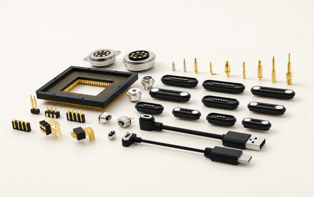
Items to Include in the Specification Review
Current per pin and for the complete interface — distinguish continuous, peak and inrush current, and verify temperature rise.
inrush currentPin count and mapping — allocate power, return, signal or ID contacts and any redundant grounds.
Contact system — define Au plating, spring force and contact-resistance stability.
Voltage, creepage and clearance — review the applicable insulation requirements, particularly above 24–48V or in a humid environment; the necessary spacing depends on the relevant application standard.
Mating arrangement — cable-to-device or PCB mounting, with the required floating or fixed interface.
Magnetic holding force — resist the expected vibration without making engagement forces damaging.
Ingress protection — distinguish IPX4 splash protection from IP67 immersion requirements and specify the corresponding sealing design.
Environment — define temperature, corrosion requirements, salt-spray duration and chemical exposure.
Reliability — specify cycle life, lateral-load tolerance and behavior under contamination.
Documentation — request applicable RoHS material evidence and organization-scope documentation for ISO 9001, ISO 14001 or IECQ QC 080000 when required; these are not interchangeable product or IP certifications.
| Required input | Why it is needed | Information for the supplier |
|---|---|---|
| Continuous current and inrush | Limits overheating and interruptions | A/pin, total A, inrush A and duration, and permitted temperature rise |
| Pin arrangement | Controls cost and fits the device structure | Device geometry and the relevant integration details |
| IP requirement | Determines the sealing approach | Actual exposure conditions rather than an unnecessarily extreme target |
| Retention force | Helps prevent unplanned separation | Pull-off target in N and the lateral-load or vibration profile |
| Operating environment | Affects corrosion, coating wear and service life | Salt-spray duration and any sweat or chemical contact |
Scroll horizontally to view every column.
Specification note: an IP68 request may call for a different size, structure and cost from a device that only needs protection against occasional splashes or an accidental fall into water. Describe actual exposure and the required protection accurately so that the design and project plan match the application.
MagtorTurning Product Requirements into a Validated Connection
Translate actual use into an electrical load specification, including inrush, a mechanical alignment and retention requirement, and an environmental protection target. Candidate assemblies then need suitable thermal, vibration and mating-life tests to check temperature and the stability of contact resistance.
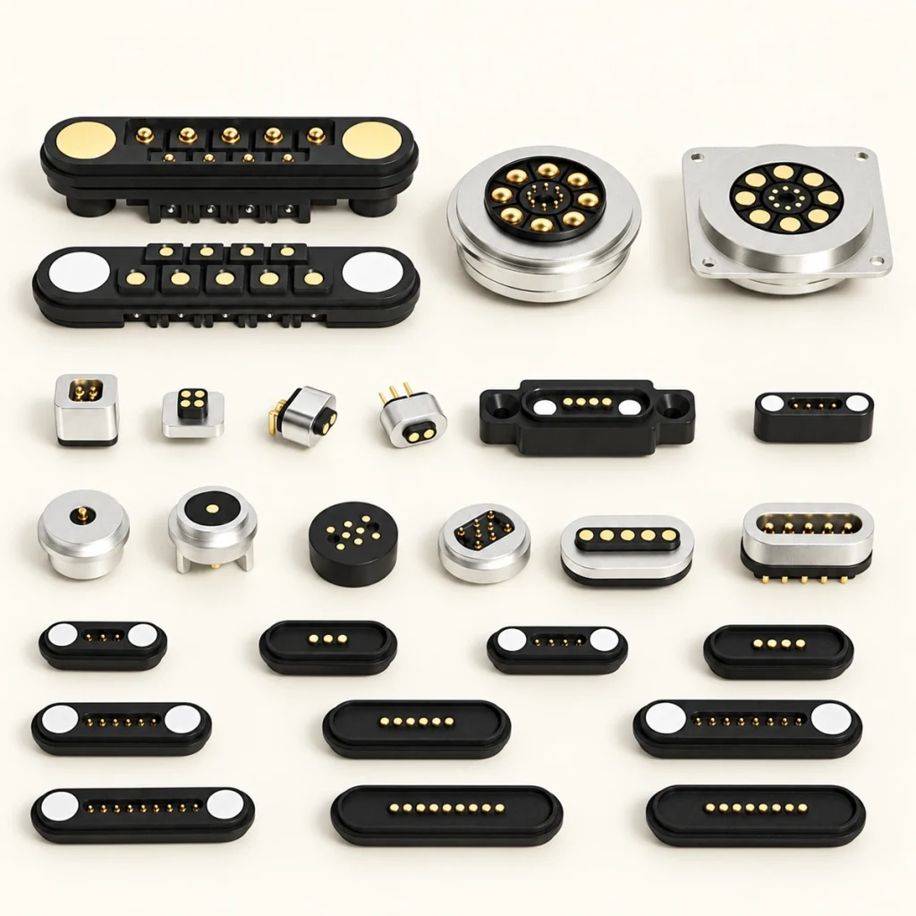
A Requirements-to-validation Workflow
Electrical load — document V, continuous A, peak and inrush current, duty cycle and allowed voltage drop.
Mechanical limits — define mating direction, available space, cable exit and acceptable pull force.
Environment — define the IP target, temperature, chemical exposure and corrosion requirements.
Candidate architecture — choose pin count, power and ground distribution, and panel, PCB or cable mounting.
Prototype validation — measure temperature rise at the worst-case load and test vibration, lateral loads and salt spray where required.
Controlled specification — agree the incoming checks for plating, spring force and contact resistance, Rcontact.
Development note: incomplete communication about the device and its requirements can lead to unsuitable samples. Give the manufacturer enough structural and operating information to choose or develop an interface that can be meaningfully tested against the real application.
Matching the Interface to Its Application
Different product categories need different electrical and mechanical performance. Those requirements influence connector size, pin count, current capacity, geometry and water protection, so the application should guide the architecture rather than the appearance alone.

Consumer products, including laptops and wearables — a slim, low-profile interface with an appropriate, moderate holding force.
magnetic connectorsHigher-power products, including power banks and medical equipment — enough contacts and current capacity for the load, with the required safety design and validation.
Industrial and automotive products — a robust interface with the specified sealing, vibration resistance and stable power transfer.
Drones and robots — higher-current requirements may suit a mix of larger power contacts and smaller signal contacts, with a custom shape and a cost-conscious layout.
Current-design note: small pogo contacts are commonly considered in the 1A–3A range in this selection discussion; check the actual model rating and thermal conditions. Higher-current requirements may call for larger contacts and revised plating or heat-dissipation provisions, which can increase size and cost.
Maintaining the Magnetic Contact System
Keep contact surfaces clean, dry and free of attracted ferrous particles. Inspect plating wear, spring movement and overmolded strain relief periodically. After wet or salty exposure, rinse only if the assembly’s maintenance instructions permit it, then dry as specified and check that seals are not cut or permanently compressed.
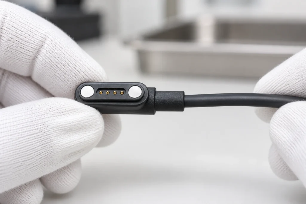
A Maintenance Checklist
Switch the equipment off before cleaning.
Remove debris with suitable nonmetallic tools; do not scrape plated contacts with metal.
Where compatible with the materials and permitted method, clean with a lint-free swab and high-purity IPA; avoid abrasive paper.
Check that each pogo pin moves smoothly and returns fully.
Inspect seals for cuts, flattening and trapped grit.
Check cable strain relief for cracking, looseness and exposed conductors.
Inspection note: iron particles can collect around the magnets and obstruct spring contacts, while liquid contamination can interfere with the pin barrel. Regular checks are especially useful in dusty environments to prevent buildup and identify contact or barrel damage before it causes intermittent operation.
Wholesale Pricing, MOQ and Production Timing
A quotation depends on pin count, current rating, IP protection, cable and overmolding requirements, plating thickness, and whether standard or custom tooling is needed. Provide the target specification and annual demand so that Magtor can discuss quantity-based pricing, MOQ, sample cost, production timing and the associated validation plan.
Information Needed for a Quotation
Electrical — voltage, continuous, peak and inrush current, duty cycle and maximum permitted temperature rise.
Configuration — pin count, power/ground/signal mapping, male or female arrangement and keying.
Environment — IP rating in the mated or unmated state, temperature range and corrosion or salt-spray target.
Integration — PCB, panel or cable mounting, conductor gauge, cable length and overmolding requirements.
Compliance and testing — required service life and applicable test standards.
Commercial planning — monthly or annual forecasts, packaging and shipping destination.
Quotation note: inaccurate or incomplete requirements can increase cost or create problems during sample testing. Drawings and structural specifications help Magtor identify a suitable standard interface or determine which parts need customization and how those changes affect the MOQ.
Start by defining the customer’s requirements and the real operating conditions, including current, service life and water protection. Then assess whether a standard connector fits. If custom development is needed, agree the estimated development time and tooling cost before moving to sample validation.