
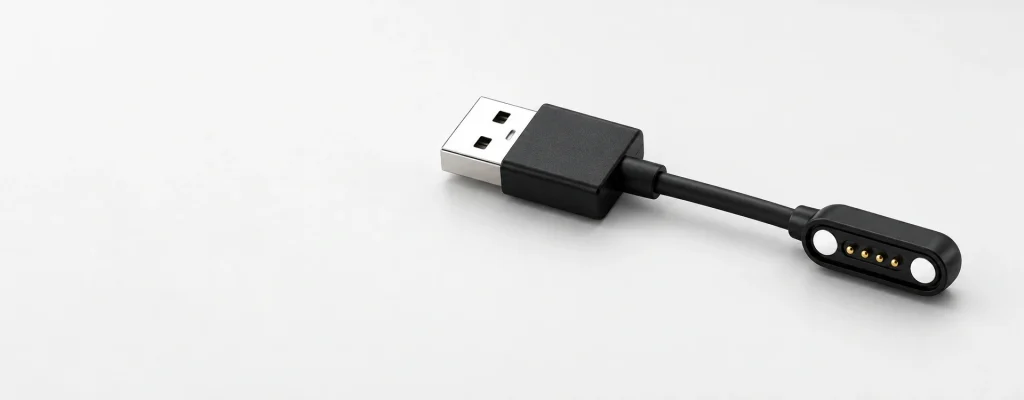
Custom Magnetic Cable Assemblies for OEM Devices
Specify a 2–16-contact magnetic pogo pin cable for power, charging, signals or ID detection. USB-A, USB-C, wire terminals and custom ends are available for device integration.
Choose the Cable Outlet Direction
90-degree and 180-degree connection formats
What Is a Magnetic Cable Connector?
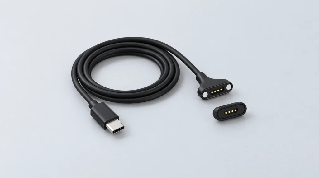
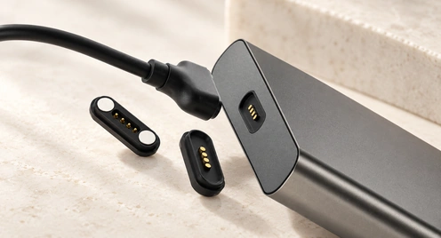
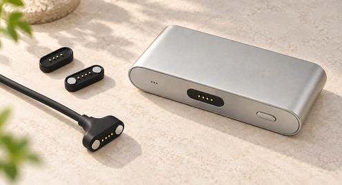
A magnetic cable assembly pairs a device-side magnetic pogo pin interface with a standard or custom power-source end, such as USB-A, USB-C, terminal leads or bare wire. The complete assembly includes the cable, unlike a standalone socket. It supports docking, charging and signals, with quick release and magnetic guidance that can reduce manual alignment and enclosure wear.
magnetic pogo pin connectorMagnetic Cable Connector Series by Pin Count
Select the contact layout for your electrical functions and device structure. Each series can be customized with the required wire gauge and cable length; different contact counts are available for project review.
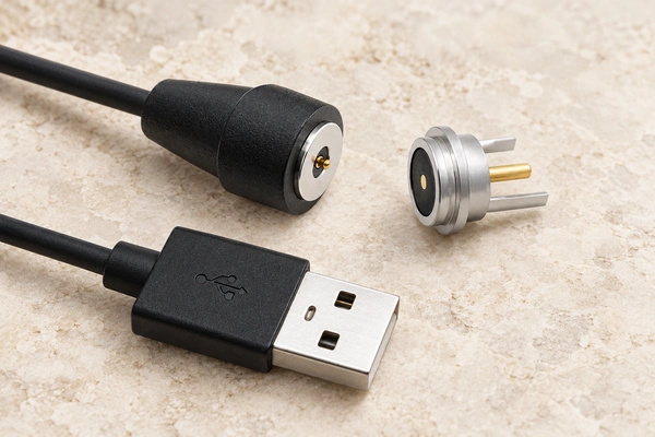
Circular Magnetic Cable Connector
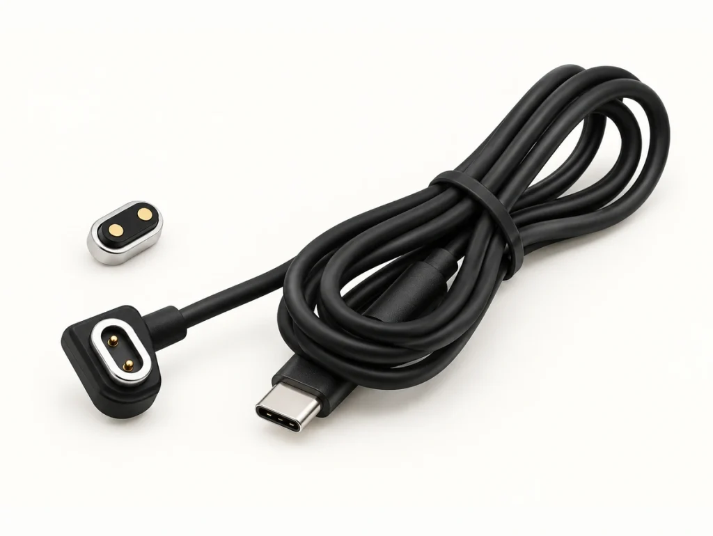
2 Pin Magnetic Cable Connector
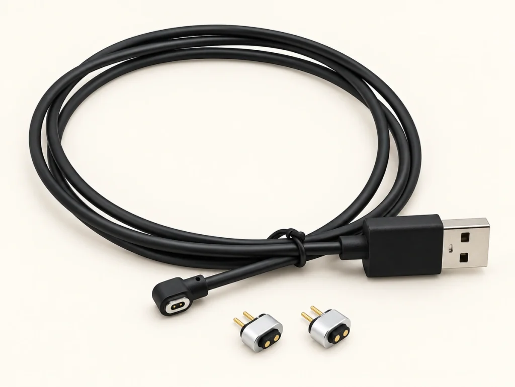
2 Pin Magnetic Connector Cable
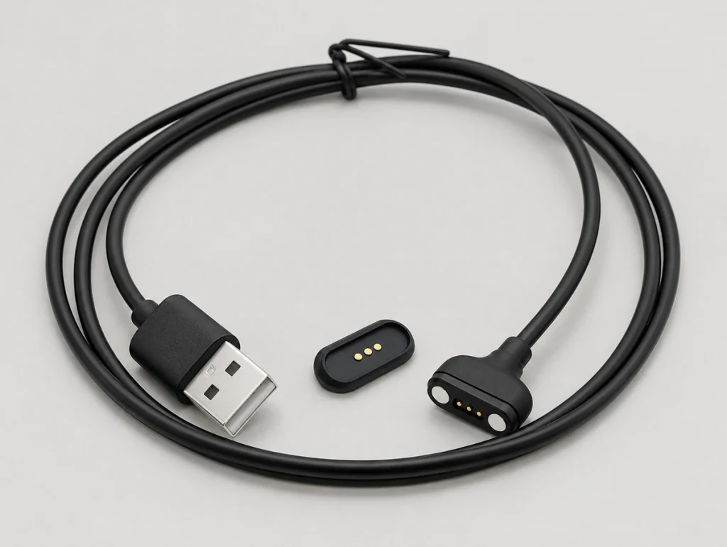
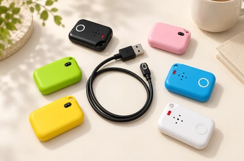
3 Pin Magnetic Cable Connector
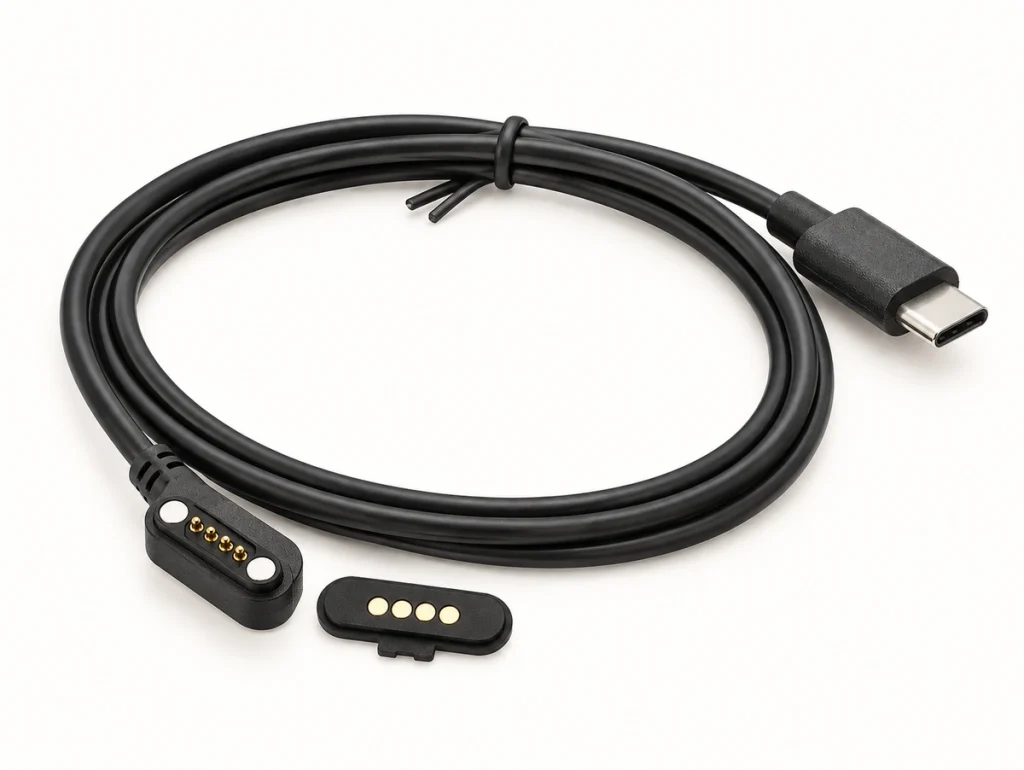
4 Pin Magnetic Cable Connector
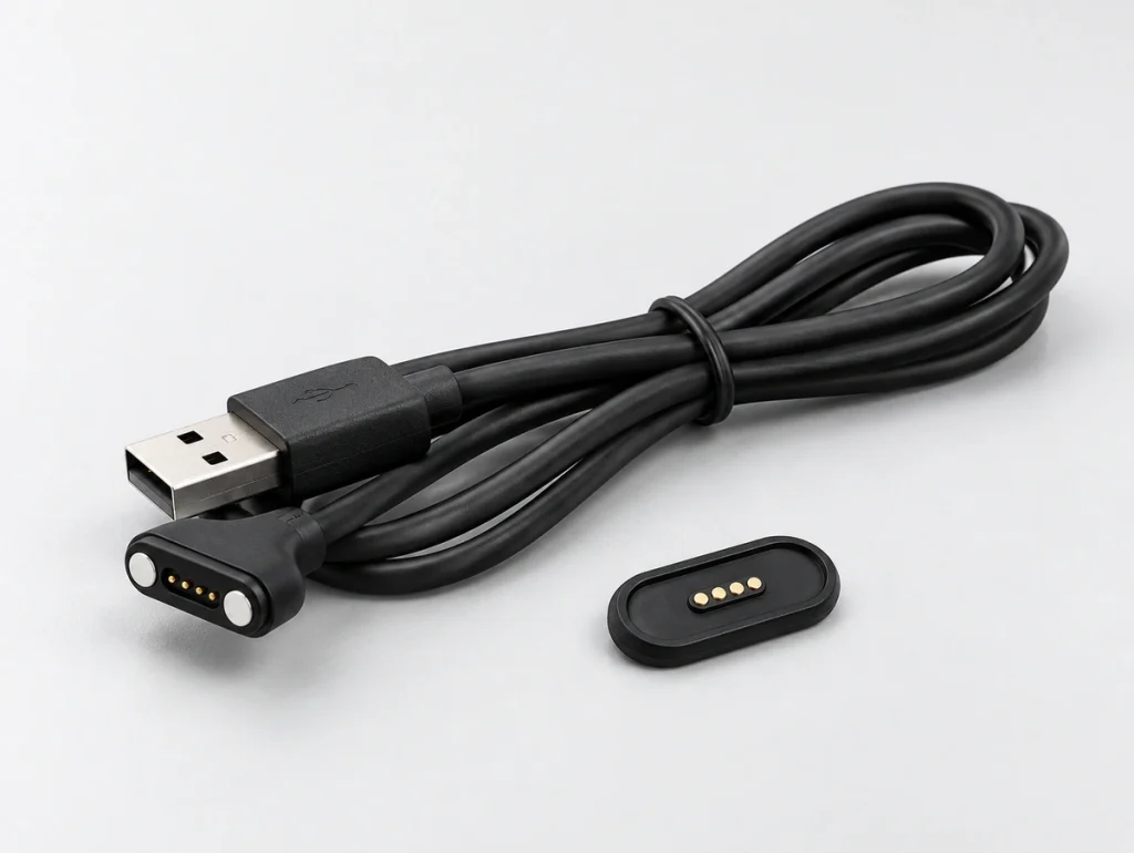
4 Pin Magnetic Connector Cable
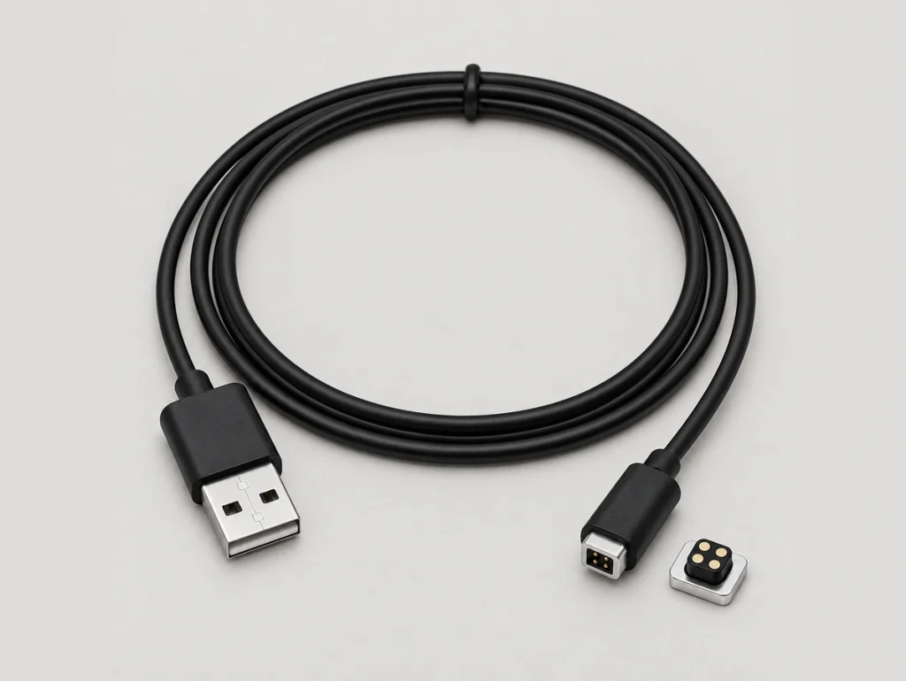
4 Pin Magnetic Cable Connector Square
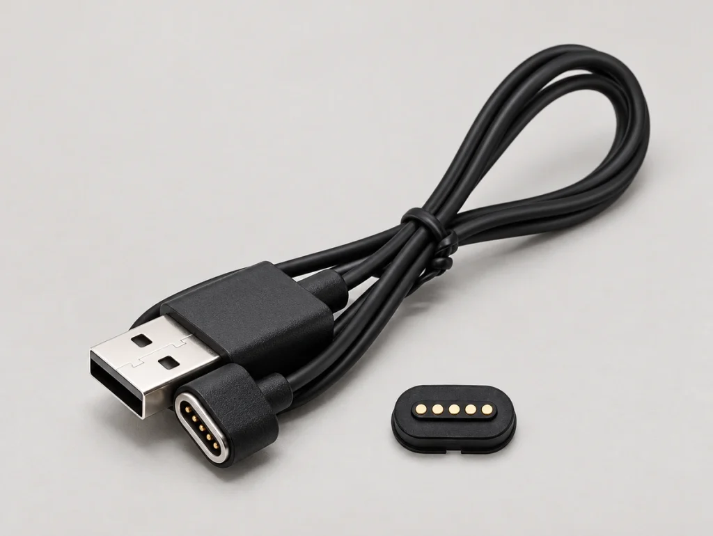
5 Pin Magnetic Cable Connector
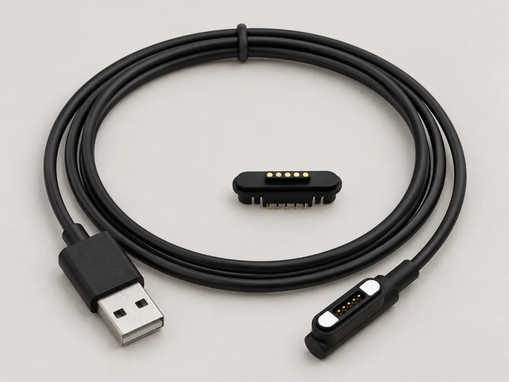
5 Pin Magnetic Connector Cable
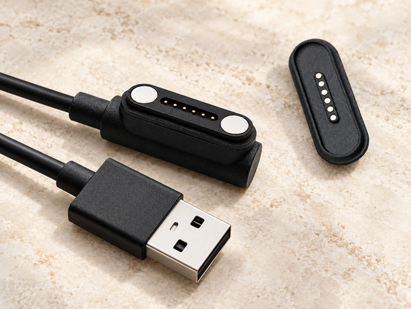
6 Pin Magnetic Cable Connector
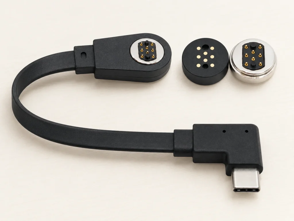
8 Pin Magnetic Cable Connector
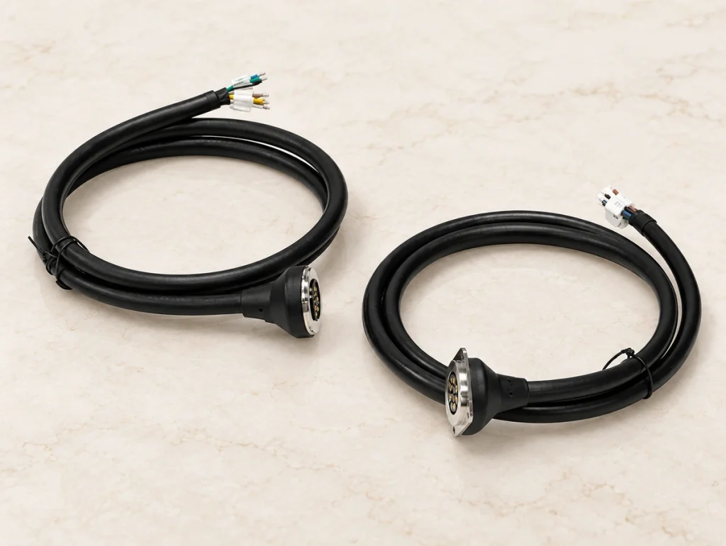
16 Pin Magnetic Cable Connector
Engineering Advantages of Magnetic Cable Assemblies
1. Prevent Cable Pull Damage in Industrial Settings
An accidental cable pull can damage an industrial or smart home device. Magnetic release helps reduce the force transferred to the interface and the risk of pulling the device over. In service, a replaceable cable can also avoid repairing the device-side pogo pin socket.
2. Simplify Blind Mating for Medical & Wearables
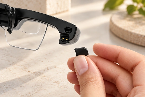
Medical and wearable equipment often needs quick charging attachment. Magnetic alignment guides connection without visual access, reducing wrong-direction mating and contact damage. The device remains responsible for its safety requirements.
3. Overcome Housing Space Constraints
A deep USB-C or DC socket may not fit a small enclosure. A custom magnetic cable head can simplify the opening, with contact assignments developed for the required power and signals.
1 / 4
Common Pin Count Selection Guide
The table shows typical configurations. Confirm the power and signal layout for the project before approving samples.
| Pin Count | Typical Pin Assignment | Common Cable End | Typical Application |
|---|---|---|---|
| 2 Pin | Power + Ground | USB-A, Bare Wire | Smart wearables, simple power connection |
| 3 Pin | Power + Ground + ID Detection | Terminal, Custom End | Handheld terminals, smart devices |
| 4 Pin | Power + Ground + 2 Signal Pins | USB-A, USB-C | Charging and communication modules |
| 5 Pin | Power + Ground + Device Detection | USB-A, USB-C, Terminal | Smart docking devices, more signal control |
| 8 Pin | Power + Signal Mixed Layout | USB-C, Custom Connector | Industrial compact electronic modules |
Scroll horizontally to view every column.
OEM Custom Magnetic Cable Assembly Capabilities
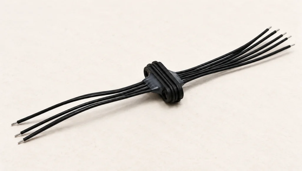
Magtor develops cable assemblies around the device-side structure. PCBA location, housing thickness and mounting holes are reviewed together so the cable head meets the electrical needs without interfering with the enclosure.
Cable length & wire gauge customization
USB-A / USB-C / terminal ends
90° or 180° cable outlet direction
Custom magnetic polarity & force
Overmolded housing design
Waterproof requirement support
Waterproof requirement
Application Scenarios & Engineering Solutions
Smart Wearables
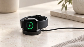
Design constraint: limited housing space, sweat exposure and frequent charging.
Suggested option: a 2Pin or 4Pin magnetic cable interface.
Expected benefit: integrate charging with fewer changes to a compact enclosure.

Medical & Healthcare
Design constraint: an easy-to-clean interface and resistance to incorrect mating.
Suggested option: a 2Pin, 3Pin or 4Pin overmolded cable.
Expected benefit: magnetic guidance supports stable charging and reduces wrong-direction docking damage.

Handheld Terminals
Design constraint: rapid docking for charging and practical field maintenance.
Suggested option: a 4Pin or 5Pin cable assembly.
Expected benefit: service teams can replace the cable rather than the terminal socket.

Smart Home Devices
Design constraint: conceal the charging interface without disrupting the exterior design.
Suggested option: a custom housing with USB or bare-wire ends.
Expected benefit: magnetic release helps reduce the risk of a device being pulled off a table.

Industrial Electronics
Design constraint: mixed power and signal circuits with frequent docking.
Suggested option: a 5Pin or 8Pin magnetic power cable.
Expected benefit: maintain contact resistance under the specified vibration conditions, subject to testing.
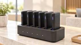
Charging Docks & Accessories
Design constraint: consistent cable batches with a defined outlet direction.
Suggested option: a 90° or 180° cable outlet.
Expected benefit: a defined structure supports repeatable pilot and volume production.
Engineering Parameters to Confirm Before Quotation
If the enclosure is already designed, send its 2D drawing, PCBA location, shell thickness and mating direction before selecting the interface. Reviewing these details helps avoid a cable head that is electrically suitable but mechanically incompatible.
Pin count & Pin pitch
Rated current and voltage
Cable length & Wire gauge
Connector end (USB/Terminal)
Magnetic force & Polarity
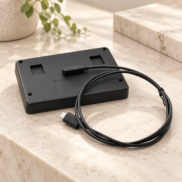
Cable outlet direction
Housing size & Mounting method
Waterproof requirement
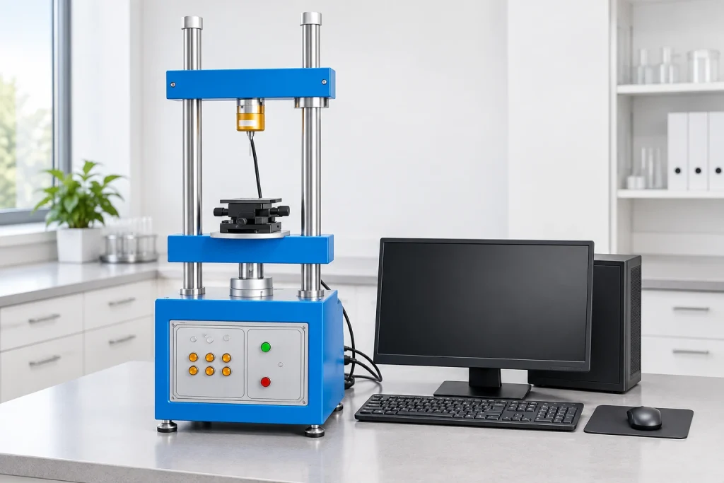
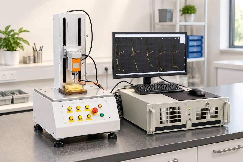
Reliability Testing for Mass Production Stability
Custom cable designs are tested within the company capability range and the limits of their structure. Checks for docking consistency and batch performance must use the conditions specified for the project.
Contact Resistance
Check resistance against the requirements for stable power transfer.
Magnetic Force Check
Measure the retention and release strength of the connection.
Life Cycle Test
Evaluate mating life within the structure-dependent 10k–100k range.
2.5D Vision Measurement
Measure contact direction and pitch with 2.5D vision equipment.

1 / 3
Magtor Cable Manufacturing Support
For an OEM device with an existing enclosure, the sample stage must confirm cable length, contact assignments, polarity and clearance. Supplying a standard cable alone does not resolve those integration requirements.
Stated founding year: 2009 — confirmation pending
Scale: 185 employees, 12 R&D staff
Facility: 12,000 m² factory area
Certifications: ISO9001, ISO14001, QC080000


1 / 2
17 Years of Connector Manufacturing
From design to mass production,
Dedicated Connector Factory
A workforce of 185 includes 12 R&D staff at our 12000-square-meter factory. This professional team supports customers with technical and manufacturing services.

Production Equipment and Technical Expertise
Our technical team works with advanced production equipment to maintain consistent connector output and performance.
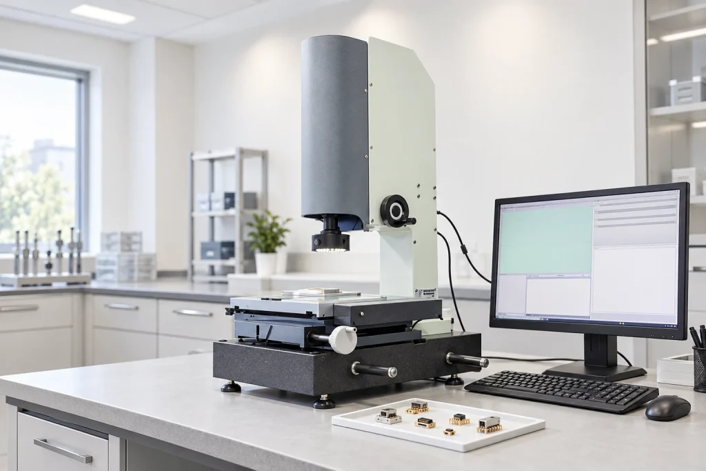
Inspection and Testing
Connector checks include lifespan, film thickness, elastic resistance, RoHS compliance and CCD inspection, using advanced test equipment.
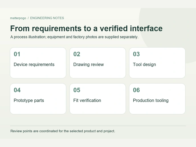
Engineering Support Customers Can Rely On
More than a dozen technical engineers review connector proposals carefully against the requirements of each application.

Automated Production
17 years of manufacturing experience support concept development through mass production, with technical guidance and prompt project responses.
Supporting More Than 500 Enterprises Worldwide










1 / 10
Management Systems and Certificate Documents

ISO 9001
ISO 14001
QC080000
Frequently Asked Questions
Can a four-contact cable use a custom pin map?
What is the difference between a magnetic connector and a magnetic cable assembly?
A magnetic connector is the device-side socket or mating plug. A cable assembly adds the specified cable length, wire gauge and termination, such as bare wire or a USB end, to create a complete power and signal connection for docking.
magnetic connectorHow do I choose between a 2 pin and 5 pin magnetic cable connector?
Two contacts suit simple power and ground connections, often in small wearables. Five contacts add paths for detection or data alongside power and ground, which can suit a smart docking station.
2 pin magnetic cable connector5 pin magnetic cable connectorDo you provide waterproof magnetic cable connectors?
Can the cable length and cable outlet direction be modified?
How is the magnetic force determined for an 8 pin magnetic cable connector?
Magnet dimensions and grade, such as N52 or a similar material, determine the available retention of an eight-contact cable. Polarity and force are selected around device weight and required release tension, balancing unintended disconnection against release during a pull.
8 pin magnetic cable connectorWhat information do I need to provide for a custom OEM magnetic charging cable?
Do you offer sample approval before mass production?
Request Cable Assembly Samples
Send the contact count, cable length, end type and current requirement. Our engineers review the drawing and recommend a suitable cable assembly.