
6-Pin Magnetic Interfaces for OEM Integration
Bring power, ground, data, ID detection and charging control into one compact magnetic interface. Custom contact assignments and repeated-use mating support devices with limited installation space.
Video material pending replacement
Compare 6-Pin Configurations and Specifications
Choose the configuration around your device structure, then review its detailed specifications below.
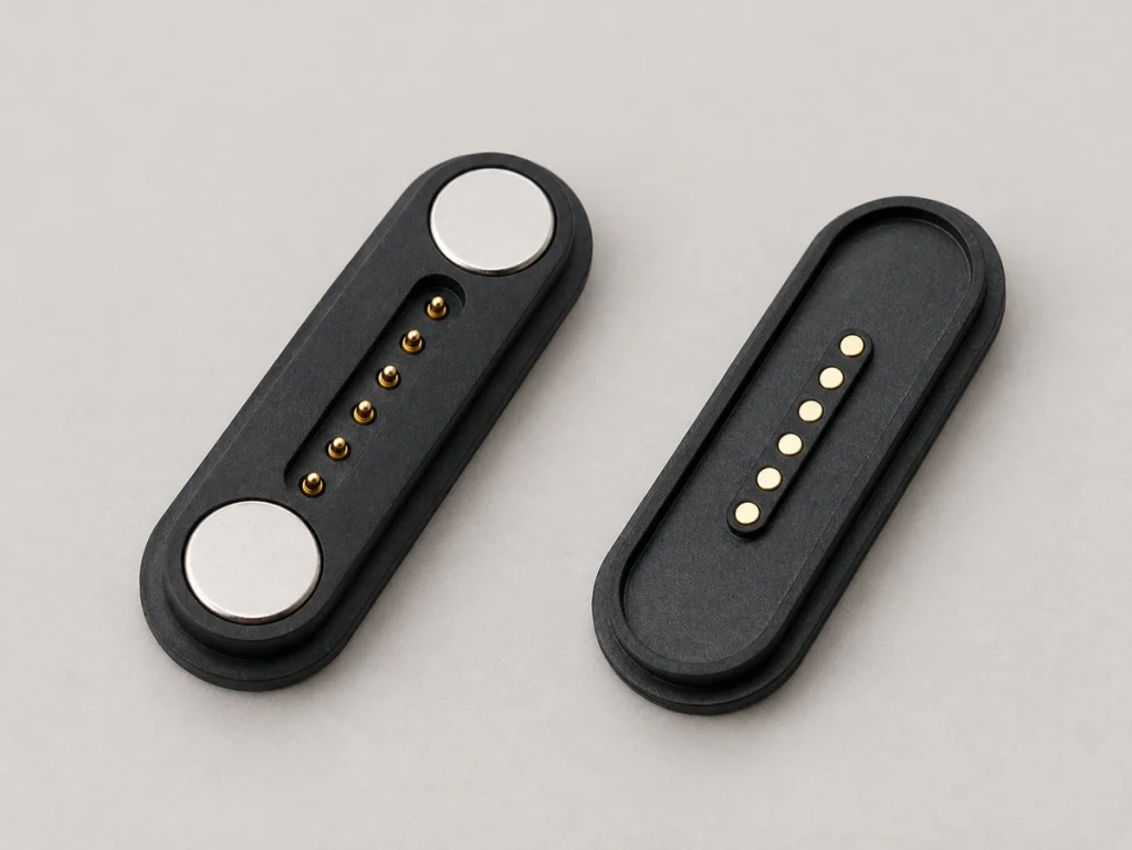
6 Pin Magnetic Connector 903-00011
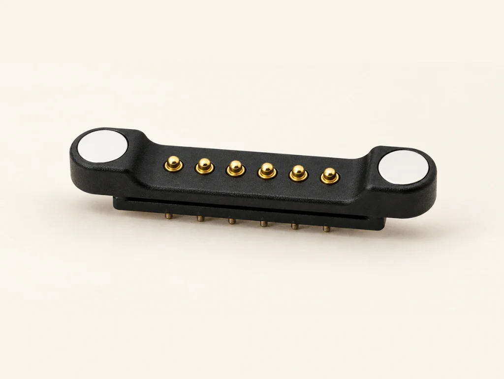
6 Pin Magnetic Pogo Pin Connector
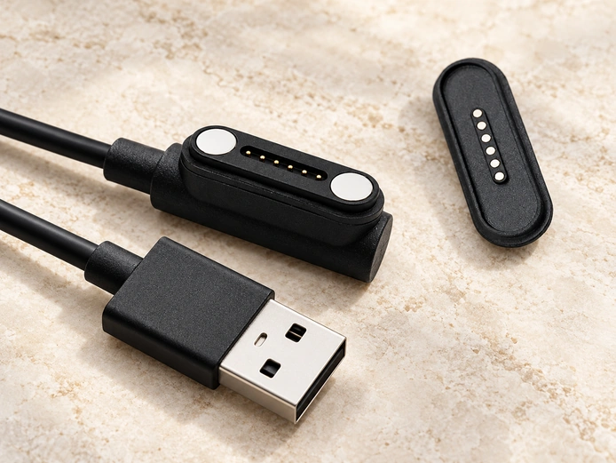
6 Pin Magnetic Cable Connector 901-00012
6 Pin Magnetic Connector vs 4 Pin and 8 Pin
The right contact count balances the functions your device needs with the space available for the interface.
4 Pin Magnetic Connector
Choose four contacts for V+, GND, basic charging or simple signals where a small footprint is the priority.
6 Pin Magnetic Connector
Six contacts can combine power, data and ID or control lines while keeping the interface compact.
8 Pin Magnetic Connector
Eight contacts allow more complex routing for firmware updates, audio, redundant power rails or multiple signals, subject to the circuit design.
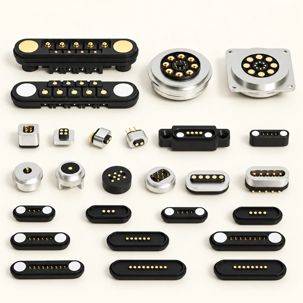
How to Define Power, Signal and ID Pins in a 6 Pin Magnetic Connector
Six-contact interfaces do not share one fixed wiring arrangement. Define the contact map around your PCBA layout and charging logic.
The contacts can serve V+, GND, data, ID detection, charging control, sensor signals or redundant power rails. We review current, voltage and signal requirements to develop an assignment that addresses EMI and mating-sequence risks; these must be verified in the completed system.
Allocate power rails around the required current distribution.
Plan ground positions to reduce signal interference.
Include project-specific ID detection for smart charging docks.
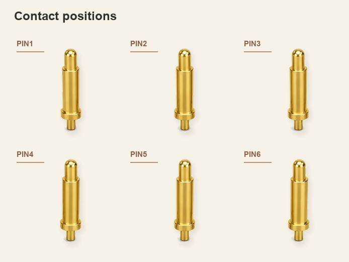
Designed Around PCBA Layout, Housing Thickness and Cable Direction
Mechanical fit matters alongside the electrical requirements. A standard interface may not match the PCBA position or housing thickness. We review the cabinet drawing and available space to define connector height and working height.
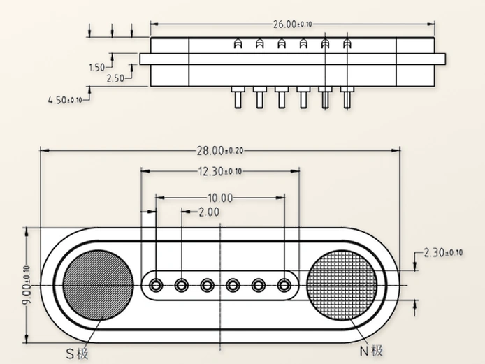
Check these structural details before sample approval:
Mounting holes alignment
Magnetic polarity matching
Mating direction constraints
Cable outlet direction (e.g., right-angle cable)
Confirming fit and orientation early helps reduce the risk of redesigning the enclosure later.

6-Pin Connector Engineering and Manufacturing
Magtor is a Dongguan-based manufacturer with operations in mainland China and Hong Kong. This series states a founding year of 2008, which remains to be confirmed against other company records. A 12,000 m² factory supports 185 employees, including 12 R&D staff. Applications include consumer electronics, wearables, medical equipment, automotive systems, smart home products and industrial devices. Long-term customer relationships include Intel, Medtronic, Huawei, Lenovo, Hisense and Sany.
Precision Design
Our in-house engineers use CAD/CAM tools to design components to the required tolerances.
Prototyping & Molds
Prototype tooling and in-house mold making help move the design through development more quickly.
Custom Solutions
Pin positions, magnetic force and housing materials can be specified for the device.
Technical Support
A dedicated field application engineering team supports integration and testing.
Specialized Factory

At the Connector Exhibition
Three visitors at a connector exhibition display.

Production Line
Controlled production with professional oversight

Quality Control
Quality checks using dedicated test instruments

Exhibition Visitors
Three visitors photographed at a connector exhibition.
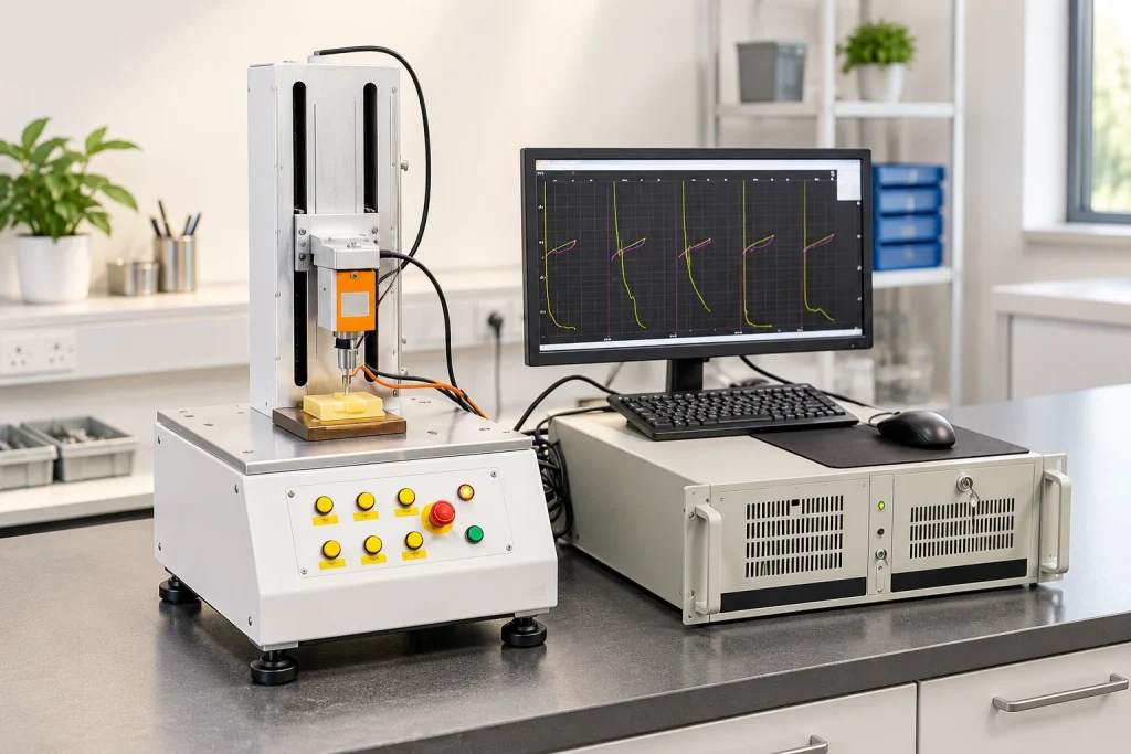
Precision Instrument Testing
Magtor works within ISO 9001, ISO 14001 and QC 080000 management systems. Critical-parameter testing is handled in-house rather than outsourced. For 6-pin interfaces, checks include salt spray, high/low temperature, pin height, contact resistance, magnetic polarity, plating thickness, dimensions, cable continuity and insertion force.
Production is supported by recorded inspection results. Batch checks include:
Incoming material inspection
Pin height & magnetic polarity check
Contact resistance testing
Plating thickness inspection
Sample approval records
Batch inspection before shipment

1 / 2
In-House Laboratory Equipment
Laboratory equipment includes a 2.5D measuring instrument, CCD inspection, automatic resistance testers, life testers, an insertion/extraction force tester, salt spray testers and a RoHS spectroscopy detector.




1 / 5
Management Systems and Certificate Documents
ISO 9001
ISO 14001
QC080000
What Is a 6 Pin Magnetic Connector?
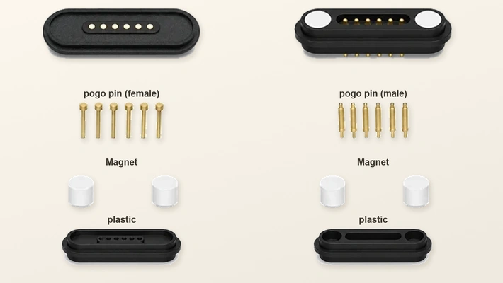
A 6-pin magnetic interface pairs male and female parts with magnetic alignment and six independent spring-loaded pogo pin contacts. It is developed for compact integration into a device.
Compared with a basic two-contact charging port, six contacts allow power to be routed alongside data, ID detection or control in one detachable interface. The PCB-side connector or cable assembly is adapted to the housing constraints and validated for power and signal performance over mating cycles.
Custom 6 Pin Magnetic Connector for OEM Projects
A custom interface follows five development stages: drawing review, structural proposal, sample approval, validation and mass production. This process addresses the fit limitations of off-the-shelf parts.
Specify contact assignments, magnetic force, working height and housing material for the application. For a full cable assembly, connector orientation, cable length, wire gauge and outlet direction can also be adjusted. Sealing or IP-rated structures may be developed where applicable.

What Affects the Cost of a 6 Pin Magnetic Connector?
Each model has its own cost structure. A project quotation considers the engineering work and procurement requirements of your specific configuration.
Contact assignments, housing tooling and working height.
Magnet dimensions, holding force and contact plating.
Cable length, wire gauge and sealing structure.
Annual volume, sample validation and packaging.
For a project evaluation, send the drawing, current and voltage requirements, operating environment, target quantity and preferred sample schedule.
FAQ About 6 Pin Magnetic Connectors
Review the technical questions used when specifying and sourcing a six-contact magnetic interface.
What is a 6 Pin Magnetic Connector?
What is a 6 Pin Magnetic Pogo Pin Connector used for?
Can a 6 Pin Magnetic Connector transmit both power and data?
How should I define the six pins?
What current and voltage can it support?
What is the difference between a 4 Pin, 6 Pin and 8 Pin?
Can you make a 6 Pin Magnetic Cable Connector?
Can the cable length and outlet direction be customized?
Is a waterproof 6 Pin Magnetic Connector available?
What causes unstable contact after repeated docking?
What information is needed for a quotation?
Can I request samples before bulk production?
Discuss Your 6-Pin Interface Requirements
For an OEM review, provide the device drawing, PCBA layout, contact assignments, voltage and current, working height and operating environment.