
5-Pin Magnetic Interfaces for Charging and Signals
Combine charging with data or signal paths in a compact device housing. Magnetic guidance aligns the interface, while pogo pin contacts provide the electrical connection.
- The design and performance can be adapted to the requirements of your equipment.
- Choose between 1.50 and 2.20 spacing options, with 90° and 180° connection formats available.
- Termination choices include USB-A, USB-C and other ports.
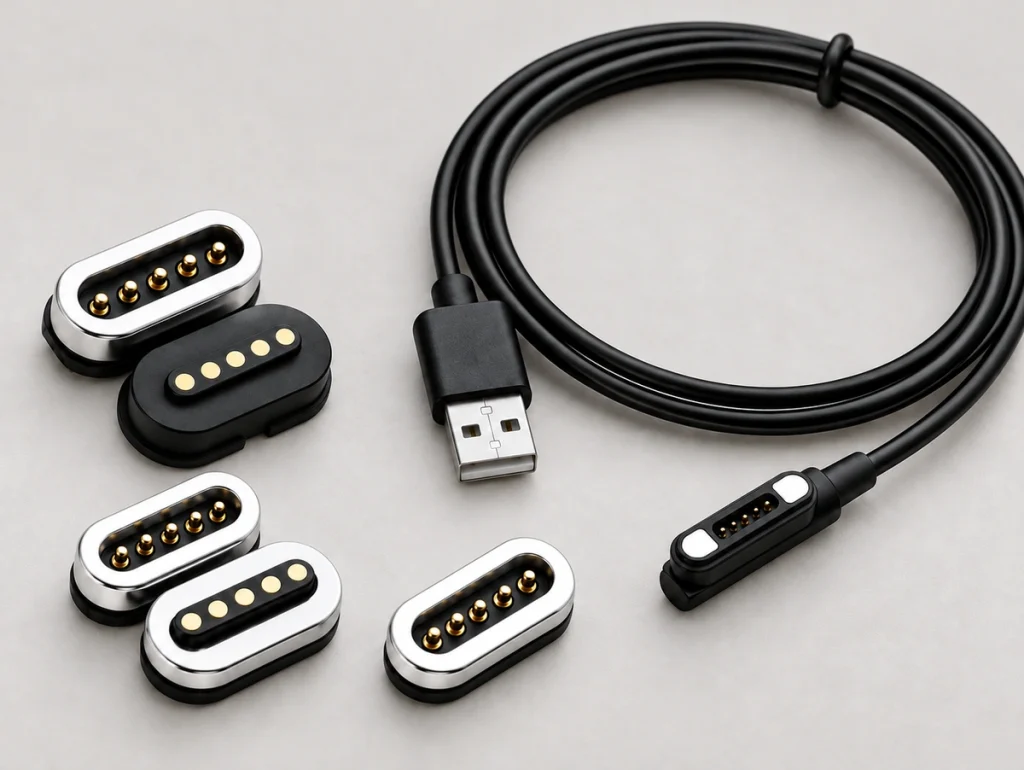
1.50PH / 2.20PH
Charging + Signal
Choose a 5-Pin Connection Format
The range includes connector pairs and magnetic cable assemblies with different routing and termination options.
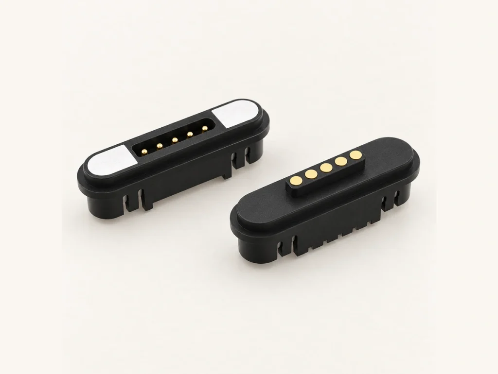
5 Pin Magnetic Charging Connector
A compact charging interface can combine power with detection or signal functions. Typical layouts include 5PIN male/female connections with 1.50-2.20PH spacing.
Custom options: pin height, magnetic polarity and PCB mounting arrangement.
Applications: wearable devices, smart home electronics and medical electronics.
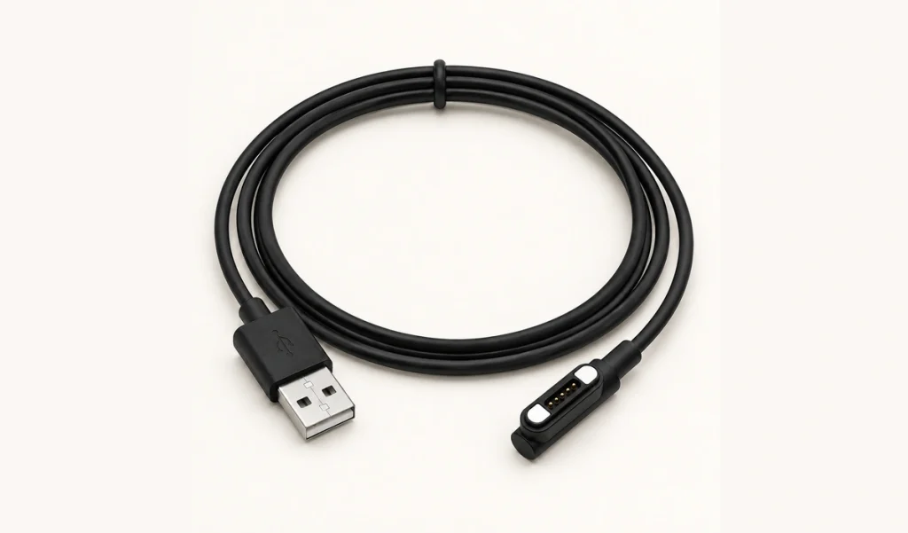
5-Pin Magnetic Cable with 90° Routing
A side-entry 90° cable arrangement carries charging and signal conductors while limiting cable bending in a compact housing.
Custom options: cable length, wire gauge, and USB-A, USB-C, bare-wire or custom-terminal ends.
Applications: devices with limited installation space or difficult cable routing.
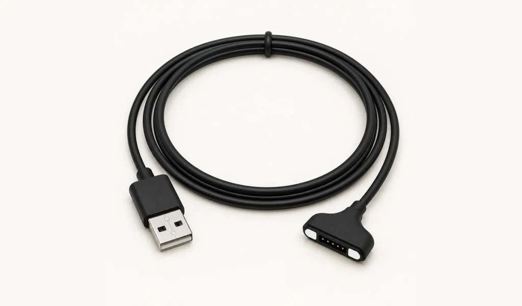
5-Pin Magnetic Cable, 180° — outlet geometry to be confirmed
The described 180° arrangement uses straight routing for an open layout, with quick magnetic attachment for charging and signals.
Custom options: cable length, wire gauge, and USB-A, USB-C, bare-wire or custom-terminal ends.
Applications: layouts that provide enough room for the cable to extend after attachment.
Listed 5-Pin Connector and Cable Models
The standard configurations below are available for evaluation. Confirm dimensions and current ratings once you have selected a model.
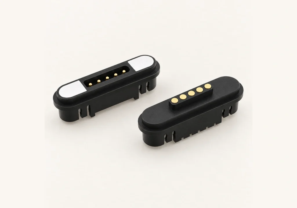
5 Pin Magnetic Connector
PN: 903-00010
Pitch: 2.20PH
Type: M/F Connector
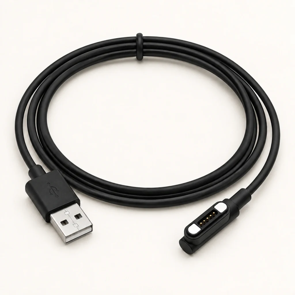
5 Pin Magnetic Cable 90°
PN: 901-00008
Pitch: 2.20PH
Type: Cable Assembly
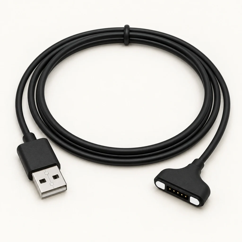
5 Pin Magnetic Cable 180°
PN: 901-00007
Pitch: 2.20PH
Type: Cable Assembly
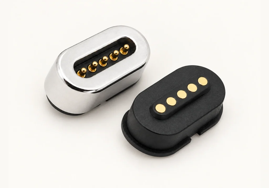
Magnetic 5 Pin Connector
PN: 904-00030
Pitch: 1.50PH
Type: M/F Connector
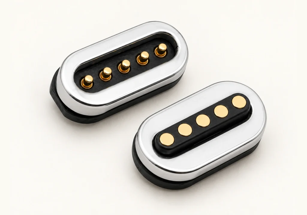
Magnetic Connector 5 Pin
PN: 904-00032
Pitch: 1.50PH
Type: M/F Connector
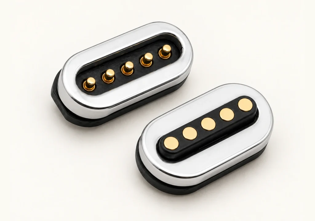
5 Pin Magnetic Connector
PN: 903-00031
Pitch: 1.50PH
Type: M/F Connector
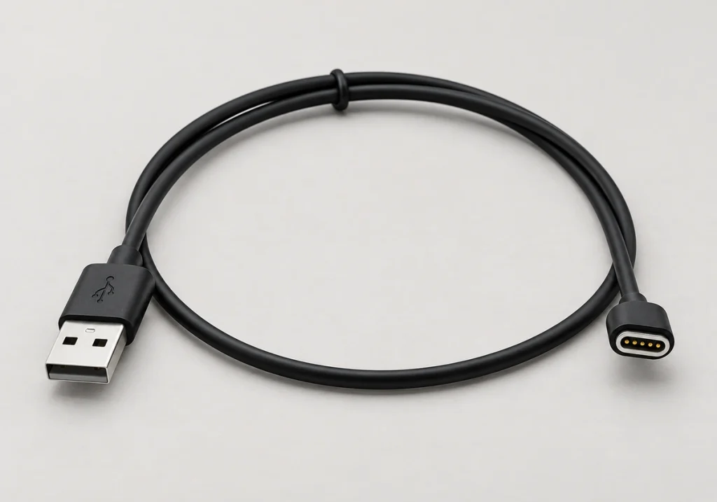
5 Pin Magnetic Cable
PN: 901-00010
Pitch: 1.50PH
Type: Cable Assembly
Connection Functions
These are general series parameters. Confirm the specific values during an engineering review of the model you select.
1 / 2
| Pin Count | 5 Pins |
|---|---|
| Pin Pitch | 1.50 mm / 2.20 mm (based on selected model) |
| Connector Type | Male (Cable/Device side) & Female (Device side) |
| Contact Type | Spring-loaded Pogo Pin |
| Mounting Method | SMT, DIP, Wire Solder (customized by project) |
| Rated Current/Voltage | Available after engineering review |
| Contact/Insulation Resistance | Confirmed during sample approval |
| Magnetic Force | Customized by project requirements |
| Durability | Based on spring force and plating specifications |
| Waterproof Option | Optional IP65/IP67/IP68 sealing design (evaluated per project) |
| Factory Certifications | ISO 9001, ISO 14001, QC 080000 |
Scroll horizontally to view every column.
Addressing Common Device Design Constraints
Review how a 5-pin magnetic interface can address engineering and sourcing constraints.
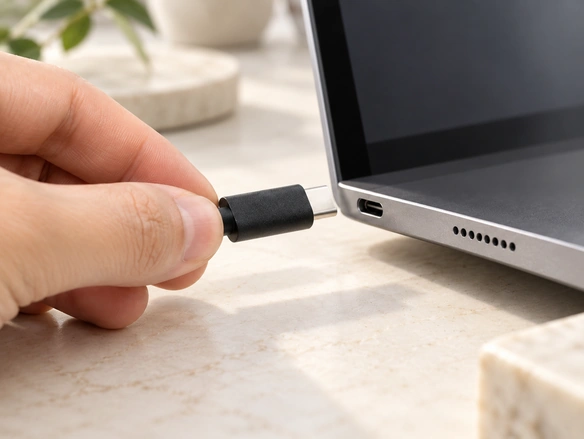
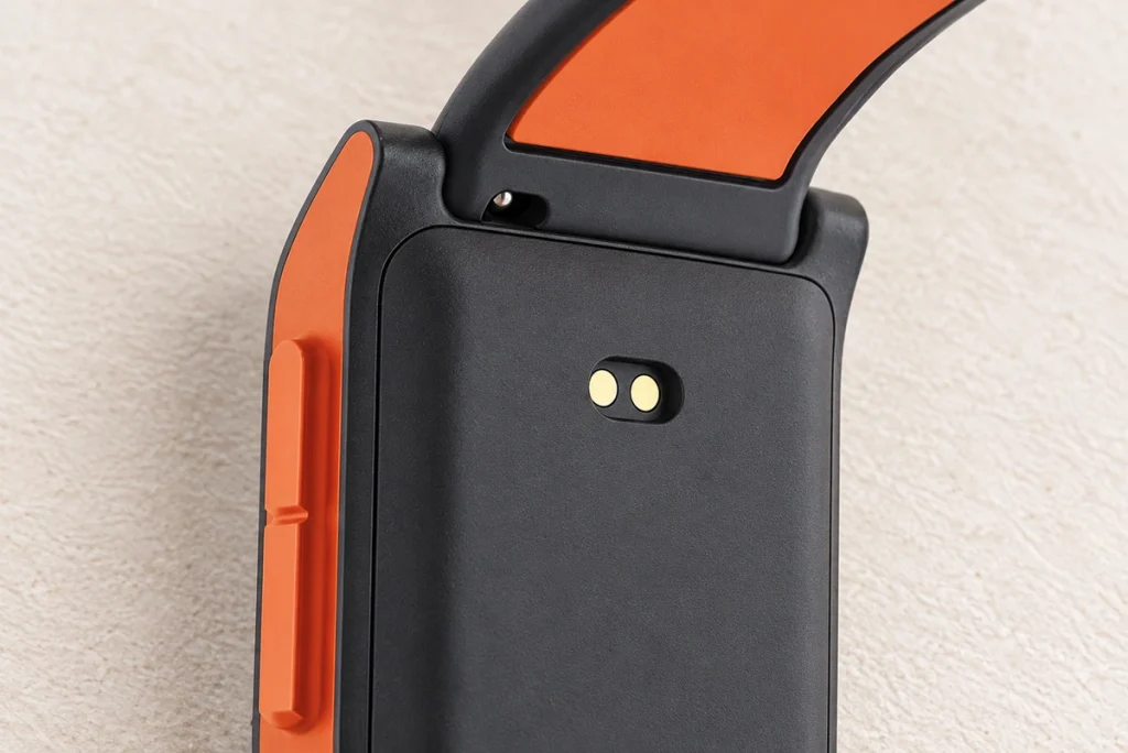
Manual Alignment & Wear
Use case: connectors for consumer electronics that are connected every day.
Design constraint: repeated USB mating can wear the interface and fatigue its contacts.
Design approach: pogo pin contacts reduce friction during docking.
Expected benefit: longer interface life and lower maintenance risk.
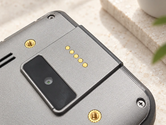
Fixed Interface Size
Use case: wearables and devices with curved housings.
Design constraint: a standard USB port can be too large or inflexible for the available space.
Design approach: define the magnetic interface dimensions around the device structure.
Expected benefit: a connection layout suited to compact spaces and unusual housing shapes.
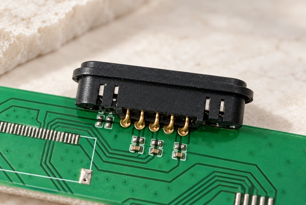
Harsh Environments
Use case: interfaces for outdoor or medical equipment.
Design constraint: dust, sweat, moisture and salt spray can impair contact quality.
Design approach: align and seal the pogo pins against the device surface, with plating selected for the environment.
Expected benefit: more stable contact resistance and reduced charging-failure risk.
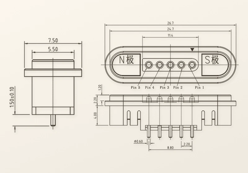
Installation Methods
Use case: selecting an installation method for a new design.
Design constraint: complex equipment makes the appropriate contact configuration difficult to choose.
Design approach: options include surface mounting, through-hole mounting, wire bonding and 90° side mounting. A 180° option is also listed, but its final routing description is incomplete and needs confirmation.
Expected benefit: an installation arrangement selected for compatibility with the equipment.
Customize the Interface Around Your Device
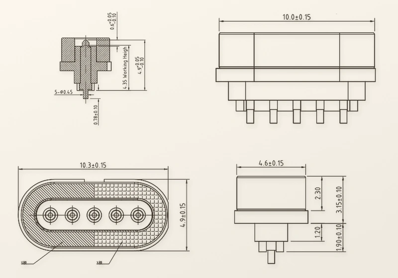
Send a cabinet drawing, a 3D housing file or the PCB layout. Our engineers review the available space and select a magnetic interface configuration around the device architecture.
The review covers housing dimensions, pin pitch, working height and mounting holes. The existing USB opening or open-frame structure informs magnetic force, male/female layout and cable outlet direction. Cable assemblies can be specified with the required wire gauge and USB-A, USB-C, DC or bare-wire ends.
Quality Assurance in Customization
Technical support continues from plating thickness and sealing design through sample approval and stable production at scale.

1 / 3
Manufacturing Capability and Batch Inspection
Magtor operates a 12,000-square-meter factory in Dongguan, China, with approximately 185 employees and a dedicated 12-person R&D team. The stated establishment year for this series is 2009 and remains to be confirmed. Listed management systems are ISO 9001, ISO 14001 and QC 080000; current new-company certificate documents are pending.
Production is supported by recorded inspection results. Batch checks include:
Incoming material inspection
Pin height & magnetic polarity check
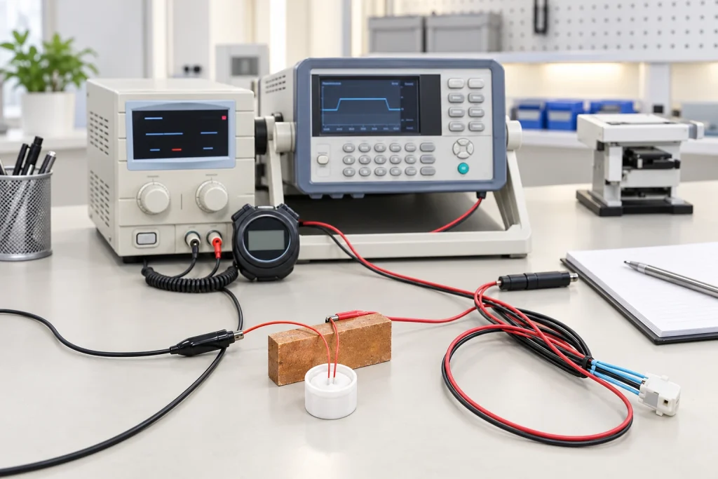
Contact resistance testing
Plating thickness inspection
Sample approval records
Batch inspection before shipment

1 / 2
In-House Laboratory Equipment
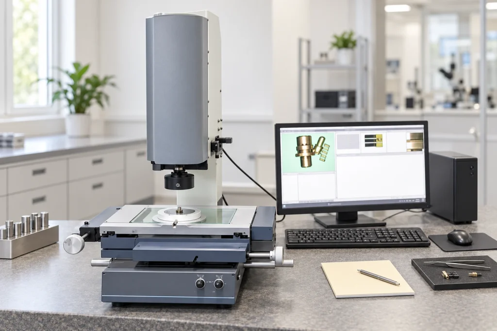
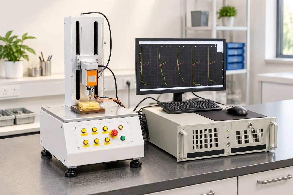
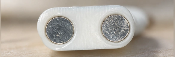
Laboratory equipment includes a 2.5D measuring instrument, CCD inspection, automatic resistance testers, life testers, an insertion/extraction force tester, salt spray testers and a RoHS spectroscopy detector.




1 / 5

1 / 3
Reliability in Harsh Environments
Sweat, moisture and cleaning residue can corrode wearable or medical charging contacts. As resistance rises, charging may become intermittent and data connections may fail.
Magtor reviews plating thickness, contact geometry and sealing before approving samples. Gold or composite plating can be evaluated using salt spray, high/low temperature and constant temperature/humidity testing to reduce contact-related field failures. Microscope inspection checks the contact surface.
Supporting More Than 500 Enterprises Worldwide










1 / 10
Management Systems and Certificate Documents
ISO 9001
ISO 14001
QC080000
Applications for a 5-Pin Interface
Different device structures use five contacts to address their own electrical and mechanical requirements.
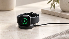
Smart Wearable Devices
A narrow wearable housing needs frequent charging. Five contacts can combine power and detection while magnetic guidance reduces alignment errors.

Medical Electronic Devices
A shallow interface is easier to disinfect than a deep port. Magnetic alignment helps staff and patients connect the device quickly; safety must be assessed for the complete medical system.
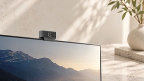
Smart Home Devices
Wall-mounted and modular smart home panels can use five contacts for power and control signals, with a flush exterior.

Handheld Terminals
An industrial scanner can be pulled or dropped during use. Magnetic cable release helps reduce force transferred to the terminal and its internal PCB.

Industrial Control Modules
Industrial control modules can combine grounding and data with project-specific contact assignments for proprietary protocols.

Pet Trackers
Outdoor pet trackers encounter dirt and moisture. A flat magnetic contact surface is easier to wipe clean than a conventional USB receptacle.

Smart Mugs & Heated Bases
Spilled liquid is a design concern for smart mugs and heated bases. An optional sealing design can address water ingress while supporting heating power.
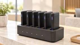
Charging Docks
For drop-and-go charging, magnetic guidance brings the portable device into place without visual alignment.
From Concept to Mass Production
Follow a defined development process to fit the 5-pin interface into the device housing.
Send Device Details
Send a cabinet drawing, 3D housing file or dimensions for the available connector space.
Confirm Specifications
Agree on contact assignments, mounting, cable length, wire gauge and sealing requirements.
Review 2D/3D Files
Review the proposed 2D drawing or 3D connector model against your device layout.
Produce Samples
Functional samples are manufactured from the approved design for physical evaluation.
Test in Housing
Evaluate alignment, magnetic retention and electrical performance with the sample installed in your housing.
Confirm Mass Production
Once samples are approved, confirm packaging, lead times and volume-production details.
5 Pin Magnetic vs. Alternatives
USB provides a standardized interface for consumer devices. A custom 5-pin magnetic pogo pin interface can be easier to adapt when the housing, mounting position or docking motion cannot accommodate the standard USB footprint.
| Comparison Factor | 5 Pin Magnetic Connector | Traditional USB Connector | Standard Pogo Pin (Non-Magnetic) |
|---|---|---|---|
| Alignment Method | Automatic via magnetic force | Manual visual alignment | Requires mechanical housing guide |
| Insertion Wear | No plug insertion; minimal mating wear | Friction causes housing/contact wear | Low wear, but requires clamping force |
| Interface Size Flexibility | Customizable | Fixed standard dimensions | Customizable |
| Waterproof Design | Easier to seal (flat mating surface) | Complex deep-port sealing required | Easier to seal |
| Charging & Signal Integration | Yes (5 pins for power, ground, data) | Yes (Standardized protocol) | Yes (Requires external locking mechanism) |
| Suitable Device Stage | Custom OEM/ODM hardware | Standard consumer electronics | Internal board-to-board connections |
Scroll horizontally to view every column.
5-Pin Interface Engineering FAQ
What is a 5 Pin Magnetic Connector used for?
How should the 5 pins be assigned?
Can a 5 Pin Magnetic Connector transmit both power and signal?
Can the connector size be customized for a small device housing?
Is a 5 Pin Magnetic Connector waterproof?
How do you reduce corrosion on magnetic pogo pin contacts?
What information is needed before requesting a drawing?
Can you provide a 5 Pin Magnetic Cable Connector with USB-C or bare wire?
What is a 5 Pin Magnetic Connector?
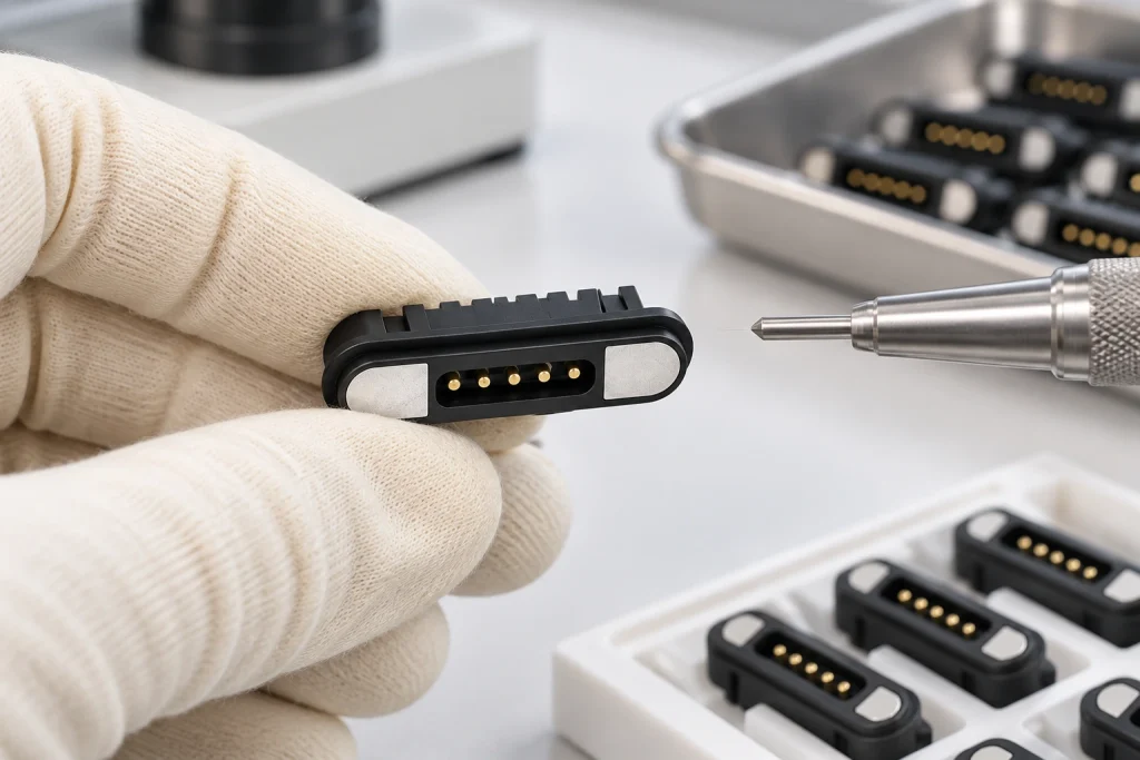
The male and female parts contain magnets for alignment and spring-loaded pogo pins for electrical contact. The parts meet without a conventional plug-in motion; magnetic retention maintains contact pressure while the springs remain under load.
Five separate contacts can be assigned to power, ground, data, detection or control. Bringing these functions into one compact interface can simplify device integration and make connection easier for the user.
Related Connector Solutions
3 Pin Magnetic Connector
A three-contact interface for current and basic data functions.
3 Pin Magnetic Connector4 Pin Magnetic Connector
A four-contact option for power and a proposed USB 2.0 data interface, subject to protocol validation.
4 Pin Magnetic ConnectorHigh Current Magnetic Connector
Dedicated high-current configurations support stable 30A transfer.
High Current Magnetic ConnectorSend Your 5 Pin Magnetic Connector Requirements
To review a 5-pin magnetic solution, send the housing drawing, contact assignments, current requirement, mounting method, sealing needs and expected sample quantity. Our engineers use those details to develop a project-specific proposal.
Direct Contact
406, Building 3, No. 12, Zhenyuan Road, Wusha, Chang'an Town, Dongguan City, Guangdong Province, China