
Eight-Contact Magnetic Connectors: Pin Maps and OEM Design
Published on September 30, 2026
- Eight-Contact Connector Architecture
- How the Mating Sequence Works
- Assigning the Eight Contacts
- Comparing Two, Four, Six and Eight Contacts
- Electrical, Mechanical and Environmental Inputs
- Potential Device Applications
- Developing a Custom Eight-Contact Interface
Eight conductive contacts with magnetic guidance can combine power, ground, data, ID and controls in a detachable interface. This architecture can suit compact OEM devices needing several circuits, with each contact's function defined by the device design.
8 pin magnetic connectorEight-Contact Connector Architecture
The interface contains eight conductive contacts and magnets that guide and retain the mating halves. Many designs place spring-loaded pogo pins on one side and flat pads on the other. As the halves approach, magnetic guidance positions them and the pins compress against the mating surfaces.
pogo pins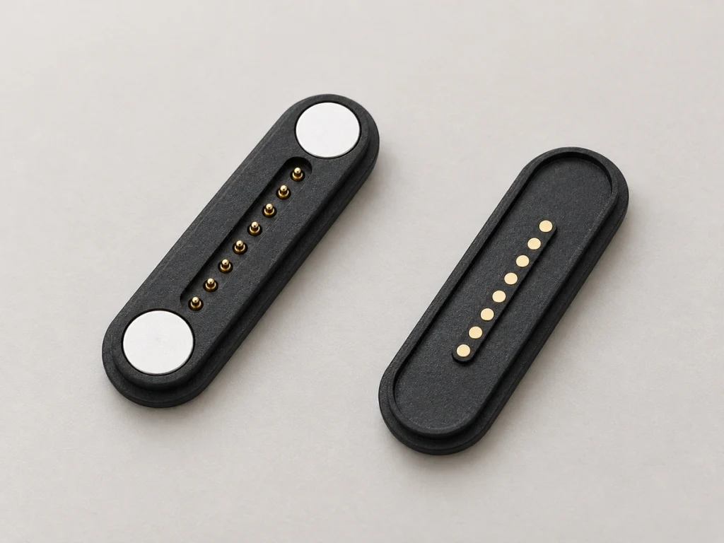
No universal assignment applies to all eight-contact connectors. A device can allocate them to power, ground, data, signals, identification, charging detection or auxiliary controls. Those options may support more functions than a basic two- or four-contact charging interface.
An eight-contact magnetic cable assembly may terminate in USB-C, bare wires, terminals or a custom end. Select that termination for the equipment-side connection rather than assuming a particular cable function from the magnetic contact count.
8 Pin Magnetic Cable ConnectorHow the Mating Sequence Works
Magnetic capture begins as the halves move toward each other and helps guide the mating surfaces into position. Mechanical locating features can complement it by limiting incorrect orientation and lateral movement.
Once positioned, the plungers compress against the pads and their springs maintain pressure while engaged. The interface provides eight physical contact paths without inserting a conventional plug; the circuit determines whether those paths remain independent or are connected together.
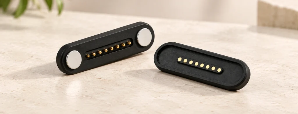
The mating process can be viewed as five stages:
Magnetic capture → mechanical positioning → pogo pin compression → conductive contact → power or signal transfer
Contact pressure and mating geometry determine performance together. Coordinate working stroke, spring force, magnet strength, housing tolerance and contact surfaces; specifying each in isolation can miss how the assembled interface behaves.
Assigning the Eight Contacts
Eight-contact magnetic interfaces have no common pinout that applies to every product. Assign each position to match the product's electrical architecture.
One hypothetical OEM assignment is shown below:
| Pin | Example Function |
|---|---|
| Pin 1 | Power V+ |
| Pin 2 | Power V+ |
| Pin 3 | Ground |
| Pin 4 | Ground |
| Pin 5 | Data / Signal |
| Pin 6 | Data / Signal |
| Pin 7 | Device ID / Detection |
| Pin 8 | Control / Auxiliary Signal |
Scroll horizontally to view every column.
Treat this map as an example only. Set the actual assignment from device voltage, current, communication, PCB architecture and safety requirements.
Some designs place power or ground contacts in parallel to distribute current. Contact count alone cannot establish allowable current or equal sharing. Evaluate pin diameter, material, plating, resistance, temperature rise, cable gauge, PCB layout and geometry for the assembled path before setting a rating.
PCB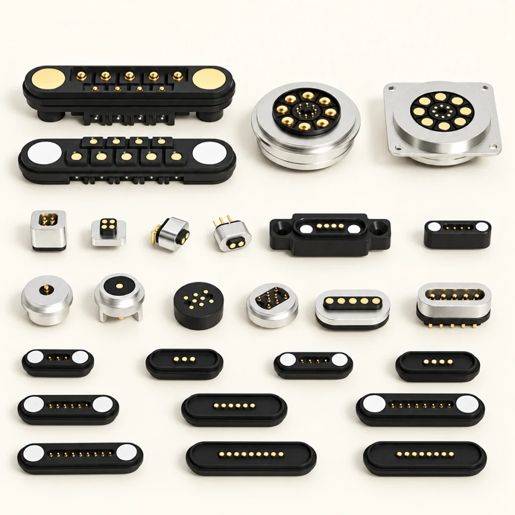
Review data transfer separately from power delivery. A pogo-based magnetic interface may carry both, but higher-speed operation needs suitable impedance, contact arrangement, grounding and PCB routing as part of the complete signal path.
Comparing Two, Four, Six and Eight Contacts
Choose contact count from the independent circuits the device needs. More contacts expand design options but do not by themselves improve performance.
Two contacts may cover basic power and ground. Three or four can add detection or simple signals, while six give more allocation options for several power, signal or identification circuits. These are architectural starting points rather than fixed pin-count functions.
2 Pin Magnetic ConnectorEight contacts can be useful when several independent functions must share one compact detachable interface.
| Contact Count | Example Allocation | Possible Design Need |
|---|---|---|
| 2 Pin | Power + Ground | Basic charging |
| 3 Pin | Power + Ground + ID/Signal | Charging with detection |
| 4 Pin | Power/return + Signal/Data | Charging with basic communication |
| 6 Pin | Multiple power and signal paths | Additional device interface functions |
| 8 Pin | Power/return + Data + ID + Control | Several OEM circuits in one interface |
Scroll horizontally to view every column.
Separate charging, communication, accessory recognition and device-control contacts can reduce the number of external connectors when the complete eight-contact design supports those functions.
Additional contacts also influence size, PCB routing, spacing, tolerance requirements and assembly complexity. Balance those five factors against the required circuits rather than selecting the highest count available.
Electrical, Mechanical and Environmental Inputs
Select the interface by combining electrical, mechanical, environmental and integration requirements.
magnetic connectorDefine operating voltage, current per circuit, the number of power contacts, resistance limits, conductor size and signals. Where contacts run in parallel, review the complete current path, sharing and thermal behavior; a single pin's rating does not establish assembly capacity.
Mechanical inputs include overall dimensions, pitch, working height, stroke, spring force, magnetic holding force, mating direction and expected cycles. Together they influence handling and contact stability over repeated use.
Specify exposure for the intended device. Wearables may meet sweat, while handheld and industrial equipment may meet dust, humidity or repeated cleaning. The following eight requirements may need application-specific evaluation:
Gold-layer thickness
Nickel barrier or alternative plating stack
Salt-fog exposure requirement
Sweat exposure requirement
Operating temperature range
Required IP65, IP67 or IP68 protection, with defined test conditions
IP65, IP67, or IP68Housing sealing design
O-ring or adhesive sealing requirements
Plan the cable early. USB-C, USB-A, bare-wire, terminal and custom ends are possible configurations. Set length, gauge and shielding, then choose a 90° or 180° exit to fit the available installation space.
Potential Device Applications
Consider eight contacts where several functions need a compact connection that is detached frequently.
Smart glasses and other wearables may combine charging with communication, device detection or accessory identification. Magnetic guidance can assist mating in a small charging area or during frequent attachment and removal, subject to the interface geometry.
Medical or healthcare designs may combine charging, signals and identification within a compact external surface. Evaluate materials, plating, cleanability, mechanical durability and environmental protection against the intended device environment; the connector architecture alone establishes no medical qualification.
Handheld industrial terminals, scanners, control units and docks may use the contacts for charging, data exchange, dock recognition and auxiliary signals. A magnetic mate can allow removal without inserting and withdrawing a conventional plug on each cycle.
Other possibilities include smart-home equipment, modular electronics, diagnostic devices, charging docks, portable instruments and equipment attached and removed repeatedly.
Base the choice on functions. Eight contacts may add complexity when only two circuits are needed, unless other design reasons justify them. Where several independent power, signal and control paths are necessary, the additional contacts can consolidate the external interface.
Developing a Custom Eight-Contact Interface
Start with the device's electrical requirements and available space. Those inputs should guide the custom interface before a connector shape is selected.
Prepare these thirteen development inputs:
Device operating voltage
Required current
Proposed contact assignment
Number of power and signal contacts
Available length, width and height
PCB layout or 2D/3D drawings
Mating direction
Required magnetic force
Water and dust protection requirements
Expected mating cycles
Cable length and wire gauge
USB-C, bare-wire, terminal or other cable end
Operating environment
Next, coordinate the pogo-pin side with its mate. Resolve contact spacing, stroke, housing tolerance, magnet location, polarity, anti-misalignment features and PCB or cable termination as one mechanical assembly.
For a sealed device, evaluate protection at housing and enclosure level. Geometry, seal grooves, adhesive, O-rings, mating surfaces and the device enclosure can all affect performance. Bare pogo pins alone do not establish a waterproof assembly.
After agreeing the structure, plan prototype checks for continuity, resistance, spring force, magnetic retention, mating durability, temperature rise, environmental exposure and dimensional consistency. These are validation activities, not evidence that an unspecified product has passed them.
Magtor can develop an OEM configuration from device drawings, contact assignments, installation space, cable requirements and environmental conditions. Engineering drawings can be reviewed before prototype manufacture so that the proposed structure is agreed first.
MagtorSelection Summary
Eight contacts can bring independent functions into a compact detachable interface. They may carry combinations of power, ground, data, signals, identification and control, with the device schematic defining the assignment rather than a universal eight-pin map.
Compare electrical load, assignments, dimensions, spring force, stroke, magnetic force, plating, water protection, mating life, PCB integration and cable ends. Those eleven factors apply to both engineering selection and purchasing review.
Providing voltage, current, a proposed map, installation space, a PCB drawing, cable configuration and environmental requirements at the start gives the engineering team a basis for selection and mechanical integration.
Discuss an Eight-Contact OEM Interface. Provide the device drawing, available space, voltage and current requirements, contact assignment, required water protection and cable configuration for structure evaluation.