
8-Pin Magnetic Cable Connectors: From Circuit Paths to OEM Integration
Published on September 29, 2026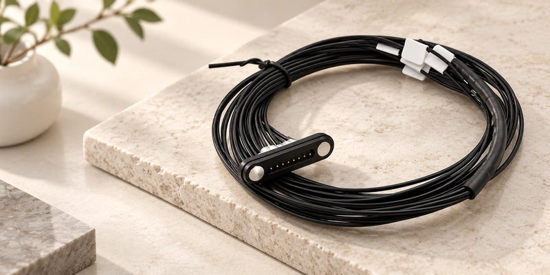
- Eight-Contact Cable Architecture
- When Additional Paths Are Useful
- Defining an Eight-Contact Pin Map
- Power and Data Conditions
- Selecting USB, Bare-Wire or Terminal Ends
- Electrical and Mechanical Design Inputs
- Choosing or Customizing the Assembly
An eight-contact magnetic cable can allocate paths to power, signals, ID, detection or control. Magnetic capture assists mating, but no universal pinout defines the functions. Specify current, cable type, magnetic force and device integration for each OEM application.
8 pin magnetic cable connectorEight-Contact Cable Architecture
The detachable assembly uses eight conductive contacts and magnetic guidance. Magnets position the halves; touching pogo pins or pads establish the electrical paths. Its opposite end may use USB-A, USB-C, bare wires, terminals or a custom connector to suit the architecture.
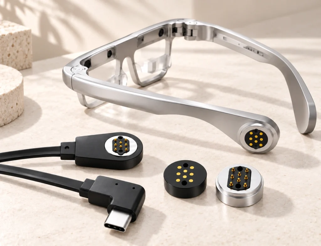
A basic two-contact cable may provide only power and ground. Eight paths can add signals, identification, control or auxiliary circuits to one compact detachable interface. Compare the broader magnetic cable connector range when selecting the count.
Magnetic Cable ConnectorWhen Additional Paths Are Useful
Begin with the circuit. V+ and GND may suffice for simple charging, while communication, detection, identification or independent controls may need more paths. Eight contacts can bring those functions together without separate connectors when the design supports them.
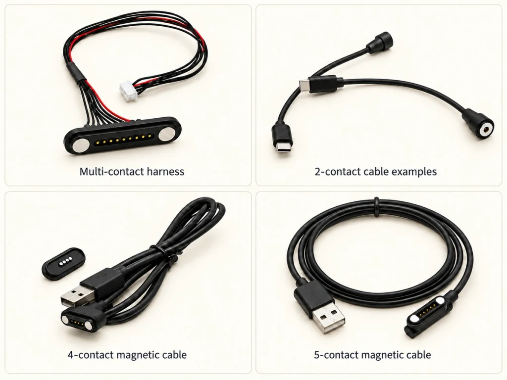
Two contacts can be a power starting point; four may add signals, and five may provide more detection or communication paths. Eight can suit several power and signal circuits in one detachable interface. These are design options, with the schematic determining the actual count.
8 Pin Magnetic Cable ConnectorDefining an Eight-Contact Pin Map
Eight pins describe physical count. One hypothetical map could assign Pin 1 to power, Pin 2 to ground, Pins 3–4 to signals, Pin 5 to ID, Pin 6 to detection, Pin 7 to control and Pin 8 to auxiliary or reserved use. Another device can use a different assignment.
Before design, define voltage, current, grounding, signals, PCB routing, connector orientation and mating direction. Cable wiring must match the device map. Different assignments, polarity, dimensions or magnetic orientation can make similar eight-contact heads incompatible.
Power and Data Conditions
Separate power and signal paths can allow charging and communication across the same interface. Eight contacts alone do not establish USB, high speed or a protocol. Review assignments, conductors, length, gauge, shielding, resistance, PCB and the electronics on both sides.
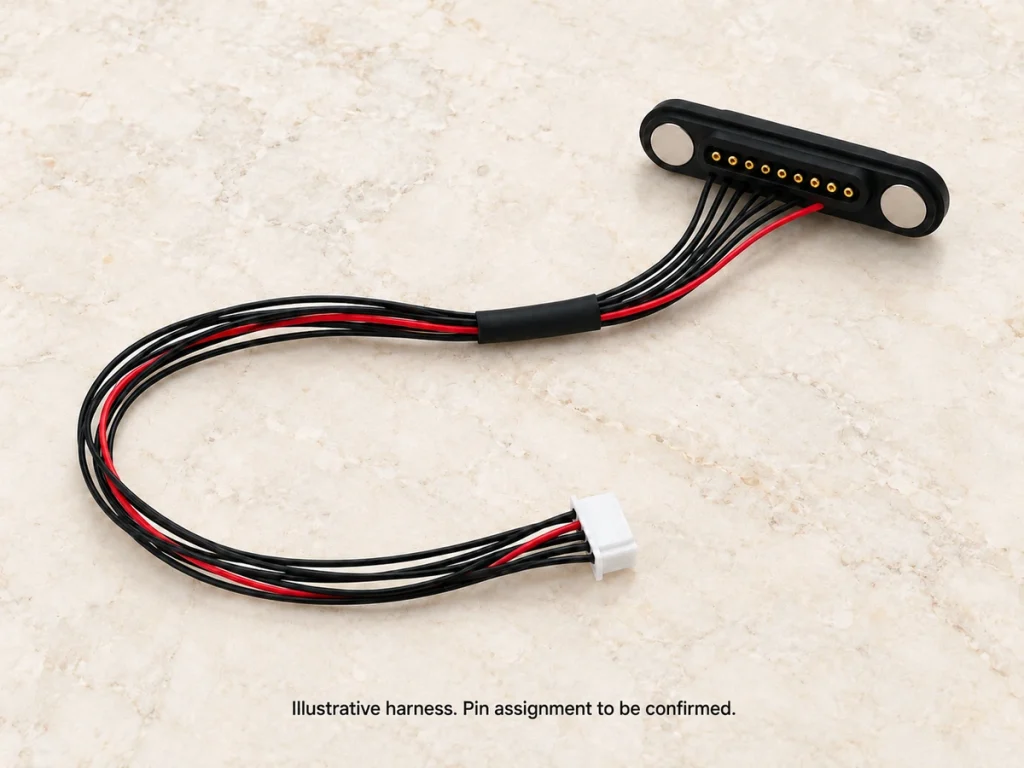
A USB-C end and the custom device-side mate are distinct interfaces. Apply Type-C connector, cable, orientation and electrical requirements on the USB side while mapping the magnetic contacts for the complete architecture. Adding a Type-C plug does not establish magnetic-side USB conformity.
USB Type-CSelecting USB, Bare-Wire or Terminal Ends
Select the end for the rest of the system. USB-C may suit a supported power source or host; USB-A may suit existing chargers, docks or equipment. Use USB-IF's Type-C cable and connector requirements for the standardized side of the assembly.
USB Type-C Cable and Connector Specification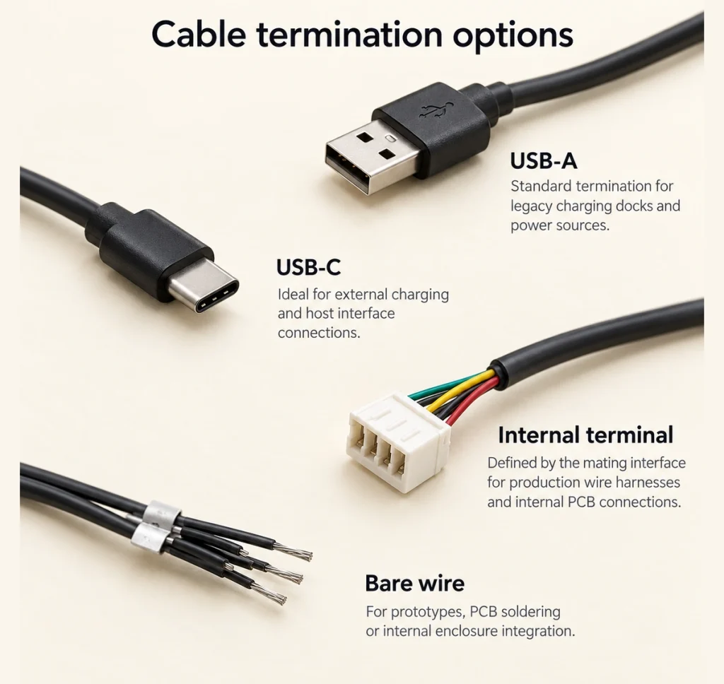
Bare wires may suit prototypes, PCB soldering or custom routing according to the pin map. Terminals or custom connectors may fit production harnesses or an existing internal system. Magtor configurations can be reviewed for both the magnetic mate and cable-end integration.
Electrical and Mechanical Design Inputs
Voltage and current inform conductor and contact selection; the signal architecture sets other assignments. Review pitch, stroke, force, resistance, length, gauge and plating against cycles and environment. Current capability belongs to the whole path, not the contact count.
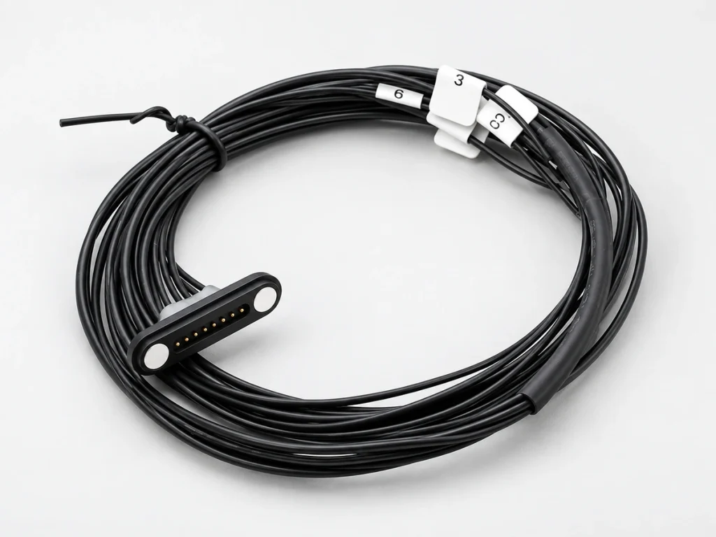
Balance contact retention with intended release. Before tooling, review housing space, orientation, 90° or 180° routing, keying, tolerances and enclosure geometry. For moisture or dust, design and validate the whole seal boundary. IEC 60529 classifies enclosure ingress protection; it does not assign a product rating from the pin design alone.
IEC 60529Choosing or Customizing the Assembly
Provide installation space, PCB position, required functions, voltage and current, length, gauge, end type, mating direction, environment, cycles and estimated production quantity. Use those eleven input groups to match the layout to the device.
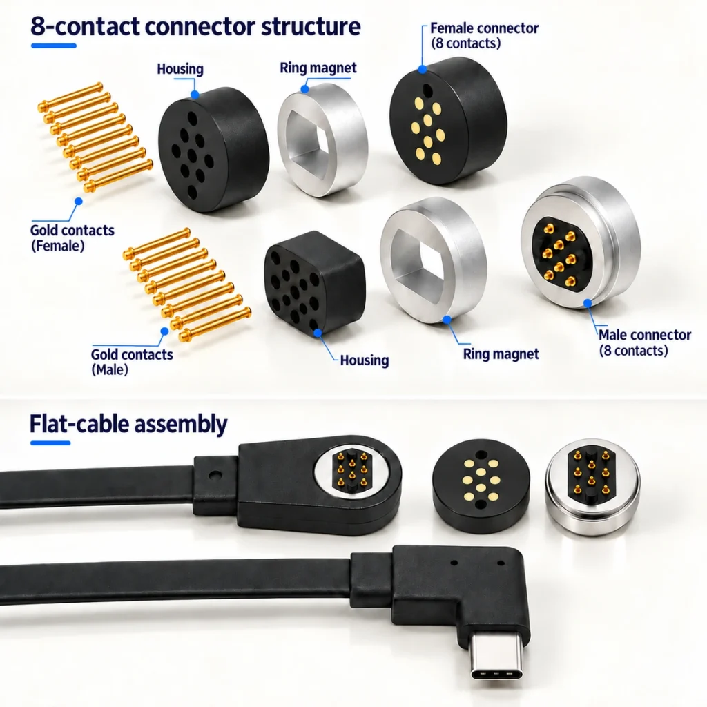
A development sequence is requirements → pin assignment → connector structure → cable design → engineering drawing → prototype → electrical and mechanical validation → pilot production. Review the Magtor eight-contact cable range when eight independent paths are needed, or the broader magnetic cable range when the count remains open.
MagtorDeveloping the Assembly Around the Device
Eight contacts can provide allocation flexibility for power, ground, signals, ID, detection and control in a compact detachable interface. Their value depends on the system's functions rather than count by itself.
Define the electrical, mechanical and environmental needs, including map, current, cable structure, geometry, magnetic force and mating details before prototyping. This can reduce redesign risk and support the transition from sample validation to production.