
Magnetic Connector Benefits and the Design Conditions Behind Them
Published on September 24, 2026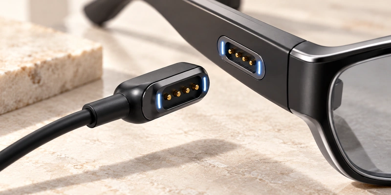
- Assisted Alignment and Docking
- Insertion Loads and Contact Wear
- Designing a Controlled Release
- Space in Compact Devices
- Sealing and Sweat Exposure
- Power and Signal Allocation
Magnetic interfaces can assist alignment, quick mating, compact integration, controlled release and power or signal allocation. They can also reduce some insertion loads. Assess these benefits for frequent charging, convenient docking or limited installation space in the intended device.
Magnetic connectorsAssisted Alignment and Docking
As the halves approach, magnetic attraction guides their initial position. Housing geometry and keying can then control final alignment and orientation before pogo pins or pads establish contact. RF and magnetic power profile's magnetic product information illustrates assisted mating in its own systems.
self-alignment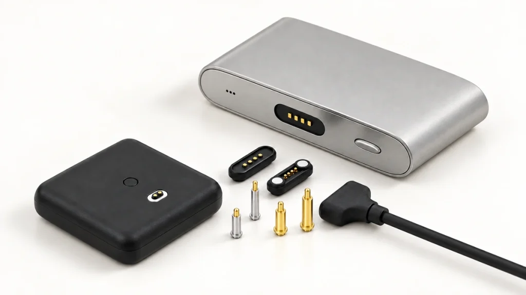
Assisted capture can be useful for blind mating or a small interface that is hard to see. The user brings the head close, and the magnetic and mechanical features guide completion. Commercial systems describe self-mating and quick connection, but each product's final positioning needs its own design.
Watches, smart glasses, docks and portable medical products may benefit from easier daily attachment.
Insertion Loads and Contact Wear
Repeated USB or barrel-plug insertion and removal applies forces to the receptacle and device housing. A magnetic interface can reduce some of those insertion-related loads, subject to its mechanical design.
Magnets guide mating while spring contacts press against the pads. Separating the magnetic interface can replace deep plug extraction, which may suit frequently connected products.
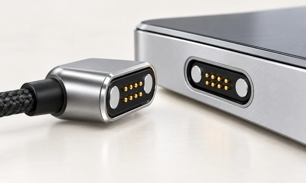
Wear remains possible. Plating, spring force, stroke, contamination and pad condition affect service performance. Define mating cycles, resistance, finish and exposure requirements before concluding that a magnetic connection will last longer.
A suitably specified magnetic cable connector can be an alternative for repeated docking that would otherwise use an inserted receptacle.
Magnetic Cable ConnectorDesigning a Controlled Release
A magnetic interface can be designed to separate when an accidental pull, snag or trip load exceeds its holding force, reducing the load passed into the device connector.
controlled breakawayControlled release may reduce stress on the housing, PCB receptacle, cable termination and solder joints. It can be useful on desktops, charging stations, medical equipment and portable products exposed to accidental pulls. RF and magnetic power profile describes controlled separation in its own magnetic interface designs.
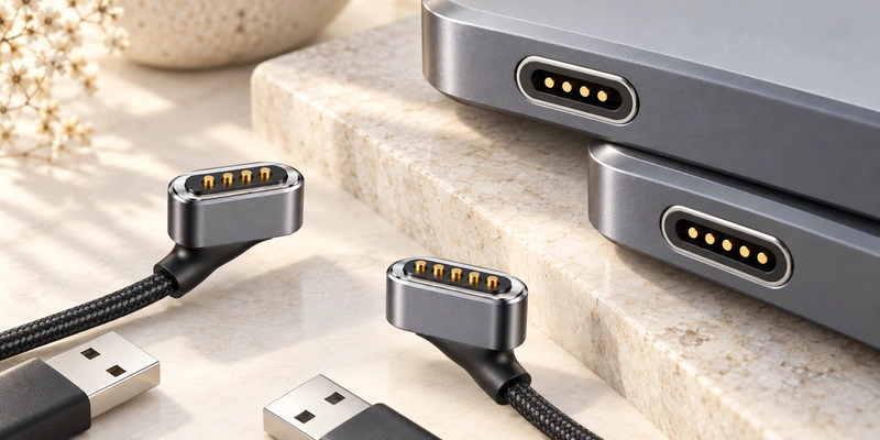
Balance retention during normal use with the intended release behavior. More magnetic force is not automatically beneficial. Consider head weight, cable direction, device orientation, spring force and expected pull loads together.
Space in Compact Devices
A surface-contact magnetic interface may reduce some space needed by a conventional receptacle body, insertion depth, retention features and insertion/removal clearance. Its final size remains design-specific.

Possible compact-device applications include:
Smart glasses
Watches and fitness trackers
Wearable medical products
Pet trackers
Compact handheld electronics
Charging cases and docks
Height and footprint depend on contact pitch, working stroke, magnet layout, PCB arrangement, housing thickness and current requirement.
Sealing and Sweat Exposure
External contacts can support a sealed-device design without a deep receptacle. Depending on the product, integration may use housing and sealing features, insert molding, adhesive, O-rings or other methods.
Magnetic capture does not establish an IP rating. Protection depends on the complete connector, housing, seal boundary, assembly process and validation.
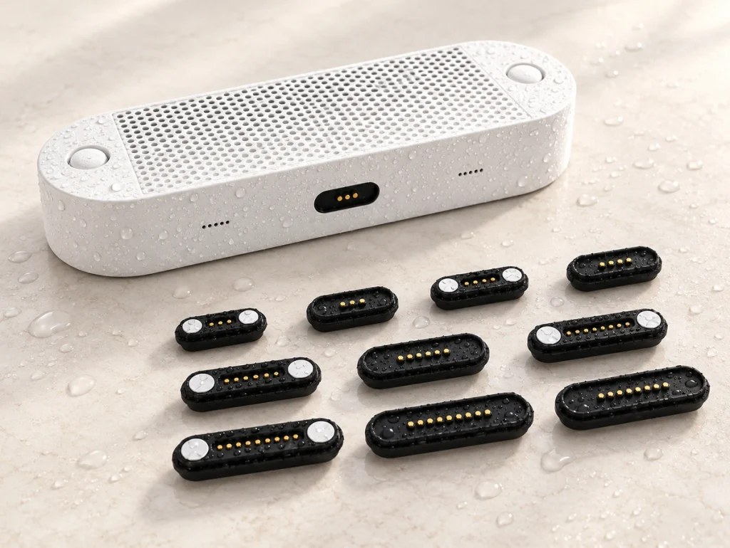
Watches, smart glasses, fitness products and medical wearables may expose contacts to sweat, moisture, skin residue and salts. Select materials and plating for those conditions.
Gold surfaces, nickel barriers and multilayer or composite finishes can be assessed for wear, sweat and electrochemical-corrosion requirements. Validate the selected surface system with the sealing design for its actual application.
This combination may suit compact charging interfaces on wearable and outdoor products that also need environmental protection.
Power and Signal Allocation
A magnetic interface may charge only or combine power, signals, data, identification, detection and control. Define contact count, assignments, wiring, geometry, electrical specifications and electronics on both sides to support the required functions.
A two-contact cable often assigns power and ground. Four contacts can add signal or detection paths; five, six or eight provide more allocation space where independent circuits are needed.
2 Pin Magnetic Charging CableThe following are possible configurations:
| Contact Count | Example Functions |
|---|---|
| 2 pins | Power and ground |
| 3 pins | Power, ground and detection or signal |
| 4 pins | Power, ground and a signal pair |
| 5 pins | Power, signals and ID or detection |
| 6 pins | Power, multiple signals and ID |
| 8 pins | Multiple power, signal and control circuits |
Scroll horizontally to view every column.
These examples do not define a universal pin map. Magtor 4-, 5-, 6- and 8-contact cables use assignments selected for the device circuit, which must be checked for the actual configuration.
MagtorFor data, define signal type, resistance, grounding, cable construction, impedance, EMI behavior and protocol requirements alongside contact count.
Applications That Justify Magnetic Capture
Identify a specific requirement for automatic docking, frequent mating, compact packaging, controlled release or a custom electrical interface before choosing magnetic capture.
| Device Requirement | Potential Design Benefit |
|---|---|
| Frequent charging | Repeated mating without conventional deep insertion |
| Blind or hard-to-see connection | Magnetic capture can assist docking |
| Compact enclosure | A low-profile contact design may reduce required space |
| Accidental cable-pull exposure | Designed breakaway may reduce mechanical loads |
| Wearable product | A compact interface can combine sealing and corrosion protection |
| Charging dock | Repeatable capture can aid positioning |
| Custom electrical interface | Contact count and assignments can be defined for the circuit |
| Power, signal and ID needs | Multiple contacts can allocate independent paths |
Scroll horizontally to view every column.
Possible applications include wearables, smart glasses, medical equipment, docks, portable electronics, smart-home products and custom OEM devices.
A standard USB interface may fit interoperability needs better. A locking connector may fit a requirement to remain attached under external force. Evaluate metallic debris, demanding high-speed signals and magnet-sensitive components separately before selecting a magnetic interface.
Realizing the Benefits Through System Design
The benefits arise from the mating mechanics: assisted alignment, controlled separation and repeated spring-contact connection. A compact multipin design can also allocate power, signals, data and identification when the electrical implementation supports them.
Coordinate pitch, working stroke, spring force, magnetic force, plating, current rating, pin assignment, sealing structure, cable design and housing for the OEM application.
With those requirements addressed, a magnetic cable connector can suit frequent charging, compact integration, convenient docking and custom power or signal connections.
Magnetic Cable Connector or Magnetic Charging Cable