
Pogo-Pin Limitations and How to Address Them in a Contact System
Published on September 18, 2026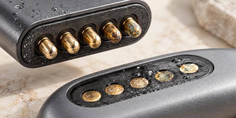
- Pogo-Pin Limitations at a Glance
- Causes of Rising Contact Resistance
- Contact Wear During Use
- Dust, Sweat and Corrosion Exposure
- Loss of Spring Force
- Current and Thermal Limits
- Controlling Alignment
- Situations That May Need Another Interface
- Reducing Contact-System Risks
- Symptoms and Troubleshooting Checks
- Spring-Loaded and Fixed Contacts
Pogo pins provide compact spring-loaded interfaces for charging, signals, docking and wearables. Wear, corrosion, spring fatigue, changing resistance, alignment and current limits are important design constraints. Suitable stroke, force, plating, contact geometry and environmental protection can reduce those risks.
Pogo-Pin Limitations at a Glance
The benefits and limitations depend on how the pin is integrated into the complete interface.
| Contact Limitation | Potential Effect | Possible Design Response |
|---|---|---|
| Contact wear | Increasing resistance | Select a suitable finish and contact force |
| Dust or contamination | Intermittent or unstable contact | Protect the area and use an approved cleaning method |
| Sweat and moisture | Corrosion risk | Assess plating and sealing for the exposure |
| Spring fatigue | Loss of contact force | Keep compression within the working range |
| Misalignment | Uneven compression or pin damage | Provide mechanical positioning |
| Small contact size | Current and thermal constraints | Assess larger contacts or validated parallel power paths |
| Precision construction | Higher component cost | Use where repeated connection justifies the design |
Scroll horizontally to view every column.
Pin diameter, overall height and advertised current are insufficient on their own. Review the mechanical and electrical interface together.
Causes of Rising Contact Resistance
Pressure between the plunger and mating surface establishes the conductive contact. Reducing the effective contact area can increase its resistance.
Possible contributors are contamination, inadequate spring force, surface oxidation, worn plating, unsuitable compression and poor pad geometry.
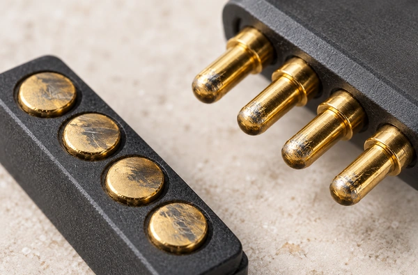
Higher resistance can create voltage drop, intermittent charging, unstable signals and extra heat while current flows.
Select sufficient force and compression for contact. Too little may leave inadequate pressure, while too much can add stress and accelerate wear.
In docks and portable products, use the specified working stroke rather than setting normal operation at maximum travel.
Contact Wear During Use
Repeatedly touching and separating a mechanical contact can produce wear on its mating surfaces.
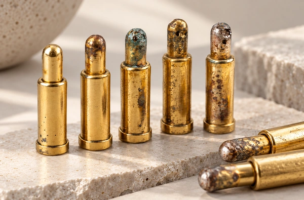
Review these factors when assessing wear:
Plating material and thickness
Spring force
Working stroke
Plunger-tip geometry
Mating-pad material
Environmental contamination
Number of mating cycles
The surface finish deserves particular attention.
Gold is commonly used for conductive, corrosion-resistant contact surfaces. It can still wear during repeated mating, especially with poorly controlled force, geometry or stroke. Gold's benefit at the surface does not make it the highest-conductivity metal.
electrical contactsSubstantial finish wear may increase resistance and expose the interface to greater corrosion risk.
Frequent docking and charging require evaluation of both mechanical cycle life and expected surface wear.
Related guide: Pogo-Pin Gold Plating, Thickness, Wear and Corrosion
Pogo Pin Gold Plating: Thickness, Wear & CorrosionDust, Sweat and Corrosion Exposure
Exposed contacts need an assessment of their operating environment.
Dust, oils, skin residue, moisture and other deposits can cover the surface and reduce effective contact area, causing intermittent charging or changing resistance.
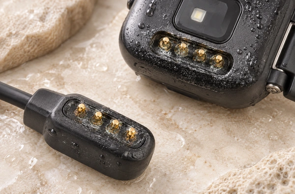
Wearables may repeatedly expose charging areas to sweat, humidity, cosmetics and skin residue.
Water and dissolved ions in sweat can promote corrosion or electrochemical reactions if the surface system is inadequately protected.
This matters for applications including:
Smartwatches, fitness trackers, medical wearables, smart rings and wearable sensors.
Assess the complete plating structure and environmental protection along with basic conductivity.
Magtor can assess multilayer or composite finishes intended to improve resistance to sweat-related corrosion and electrochemical degradation, with validation for the chosen contact and exposure.
Where needed, include housing geometry, sealing and mating-surface protection in the design.
Related guide: Preventing Charging-Contact Corrosion in Wearable Devices
How to Prevent Charging Contact Corrosion in Wearable DevicesLoss of Spring Force
The internal spring keeps the plunger pressed against the mating surface within the intended operating range.
Repeated use outside the compression range can add mechanical stress, potentially reducing spring force or making electrical contact less consistent.
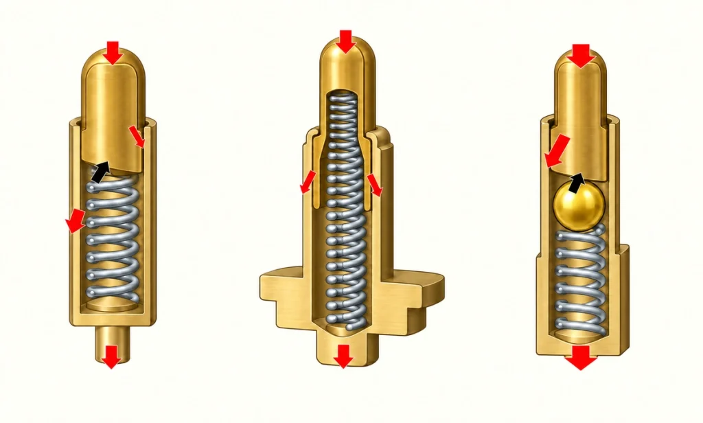
Keep total travel and recommended working stroke as separate design specifications.
They describe different operating limits.
Total stroke is the plunger's maximum available mechanical travel.
Working stroke is the compression range intended for operation in the finished product.
Manufacturing tolerances, PCB height, housing dimensions, pad position and assembly variation must collectively keep compression within the recommended range.
In a multipin interface, housing variation or an angled mate may compress some contacts more than others.
Current and Thermal Limits
Pogo pins can carry charging current, but the allowable load is specific to their contact design.
Small pins offer limited conductive cross-section and contact area. Resistive heating rises with electrical load, so review diameter, internal construction, resistance, materials, wiring, PCB copper and heat dissipation.
Different pogo-pin designs have different current capabilities.
Small contacts may suit lower-current electronics, while larger or purpose-designed contacts can be evaluated for higher loads.
For higher-power designs, possible measures include:
Larger-diameter contacts
Optimized internal conductive structures
Parallel power contacts with validated current sharing and temperature rise
Suitable wire gauges
Larger PCB copper areas
Dedicated high-current pogo-pin designs
Magtor offers contact-design options for compact electronic products and specialized high-current magnetic interfaces.
high-current magnetic connectorValidate current capability at the actual working stroke, ambient temperature, mating condition and duty cycle, in addition to reviewing the stated rating.
Controlling Alignment
Axial plunger travel can absorb a designed amount of height variation. It cannot compensate for unlimited lateral offset or angular misalignment.
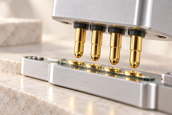
Excessive lateral loading may produce:
Uneven compression, plunger friction, unstable contact, pad wear or mechanical damage.
Multipin interfaces need particular attention to this alignment.
The housing should set the final position, while the pins establish electrical contact and absorb the designed compression tolerance.
Magnets can assist the approach in a magnetic interface, but suitable mechanical geometry still needs to control the final mating position.
Review pins, pads, housing, positioning features, PCB tolerances and compression as one interface.
Related product range: Magnetic Cable Connectors
Magnetic Cable ConnectorSituations That May Need Another Interface
Pogo pins can suit compact size, repeated mating, axial compliance, convenient docking and exposed charging. Suitability still depends on the individual connection.
A permanently connected circuit may be served more economically by a soldered wire, PCB connection or fixed terminal.
Consider alternatives for extremely high continuous current, high voltage, uncontrolled severe contamination, strong lateral loads or contacts that cannot be adequately protected.
Use reliability as an application-specific question:
Can a pogo-pin interface be reliable?
Then define the conditions that the device needs:
Does the selected interface meet this device's electrical, mechanical, environmental and lifetime requirements?
With suitable selection and integration, pogo pins can serve docks, wearables, modular devices, medical electronics, test fixtures and magnetic charging interfaces.
A conventional USB interface may be more appropriate when standardized power and data compatibility across devices is a frequent requirement.
USB connectorReducing Contact-System Risks
Address contact-system risks during connector design to reduce avoidable reliability problems.
Review the following design inputs:
Working stroke: Set normal compression inside the recommended range, rather than at the mechanical travel limit.
Spring force: Provide enough pressure for electrical contact while limiting unnecessary mechanical stress.
Contact plating: Choose material and thickness for the required cycles, current, humidity, sweat exposure and corrosion conditions.
Pin diameter and current path: Match dimensions and internal construction to the load and permitted temperature rise.
Mating-pad design: Provide adequate contact area and a finish compatible with the intended contact system.
Mechanical alignment: Use housing geometry or locating features to control lateral and angular movement.
Environmental protection: Assess sealing, corrosion-resistant finishes and contamination control for outdoor, wearable, medical or high-humidity use.
Select the pin as part of that complete interface and its operating conditions.
Symptoms and Troubleshooting Checks
Device symptoms can offer clues, but more than one contact-system fault may produce the same symptom.
| Observed Symptom | Possible Contributor | Checks to Perform |
|---|---|---|
| Intermittent charging | Deposits or insufficient contact force | Inspect the surface and working compression |
| Connector heating | High resistance or excessive current | Measure load, contact resistance and temperature rise |
| Pin does not return | Plunger obstruction or spring damage | Inspect movement and contamination |
| Contact corrosion | Moisture, sweat or an unsuitable finish | Review plating and environmental protection |
| Uneven multipin contact | Mechanical tolerance variation | Check coplanarity and housing alignment |
| Excessive pad wear | High force or over-compression | Check spring force and working stroke |
| Voltage drop | Increased contact resistance | Review finish condition, deposits and the current path |
Scroll horizontally to view every column.
Combine electrical measurements with mechanical inspection when investigating a pogo-pin connection.
Spring-Loaded and Fixed Contacts
Pogo pins supply spring-loaded movement. Fixed contacts generally obtain mating pressure and alignment from the surrounding connector geometry.
| Comparison Factor | Pogo-Pin Contact | Fixed Contact |
|---|---|---|
| Spring-loaded movement | Provided by the pin | Usually absent from the contact itself |
| Repeated docking | Can be well suited | Depends on the interface design |
| Tolerance compensation | Available within the axial working range | More dependent on surrounding geometry |
| Mechanical wear | Possible during mating | Can be lower in suitable designs |
| Contact pressure | Set through spring compression | Set through connector geometry |
| Environmental exposure | Needs protection appropriate to the application | Depends on design and exposure |
| Component complexity | Includes moving contact parts | Often fewer moving parts |
| Customization | Available through contact design | Depends on connector type |
Scroll horizontally to view every column.
Choose according to mating frequency, available space, movement tolerance, current, environment and intended product life.
Frequently Asked Questions
What is the main limitation of a pogo-pin interface?
Its performance is sensitive to compression and surface condition. Incorrect stroke, contamination, worn plating or poor alignment can increase resistance and reduce contact reliability.
How is a pogo pin's life determined?
Structure, working stroke, spring force, finish, mating surface, environment and test conditions all matter. Confirm a specific model's mechanical-cycle rating and its conditions instead of applying a universal life value.
What can cause a pogo-pin connection to fail?
Possible causes include contamination, corrosion, plating wear, inadequate or excessive compression, spring degradation, lateral load, mechanical misalignment and electrical overload.
Can exposed pogo-pin contacts corrode?
Yes. Moisture, sweat, salts and other deposits can affect exposed metal. Appropriate plating, connector protection and environmental design can reduce the risk.
Can a pogo pin be designed for high current?
Yes, with a suitable design. Size, resistance, materials, internal conductive path, wiring, PCB layout, working compression and thermal conditions determine load capability. Select and test the contacts for the required high-current conditions.
Are pogo pins an option for wearables?
Their compact form can provide a charging connection without a conventional plug. Review sweat exposure, corrosion protection, working stroke, force and housing sealing carefully for the specific wearable.
Selecting and Validating the Interface
Pogo pins combine small size, repeatable spring contact and flexible integration with constraints. Wear, contamination, corrosion, spring fatigue, alignment and current-related heating can affect performance if the design does not manage them.
Evaluate the pogo pin within the complete electromechanical system.
Suitable stroke, force, plating, current capacity, pads, housing alignment and environmental protection can reduce faults and support reliability during service.
A properly integrated pogo-pin interface remains an option for repeated charging, docking, modular connection and compact electrical interfaces.