
Magnetic and Standard Pogo-Pin Connectors: Choosing the Mating System
Published on September 17, 2026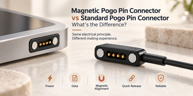
- The Difference in Mating Architecture
- How Both Contact Systems Work
- Alignment and Retention
- Working Stroke and Contact Stability
- Durability, Vibration and Breakaway
- Design Trade-Offs When Adding Magnets
- Choosing for the Device's Requirements
Both magnetic and standard pogo-pin connectors use spring-loaded electrical contacts. Standard interfaces obtain alignment and retention from mechanical features; magnetic designs add capture and holding force for docking and release. Choose according to stroke, retention, mating frequency and the device's requirements.
The Difference in Mating Architecture
In a standard interface, mechanical positioning brings the mating surfaces together and the spring pins maintain pressure. A magnetic version adds attraction to help capture and retain the halves while using the same contact principle.
magnetic pogo pin connector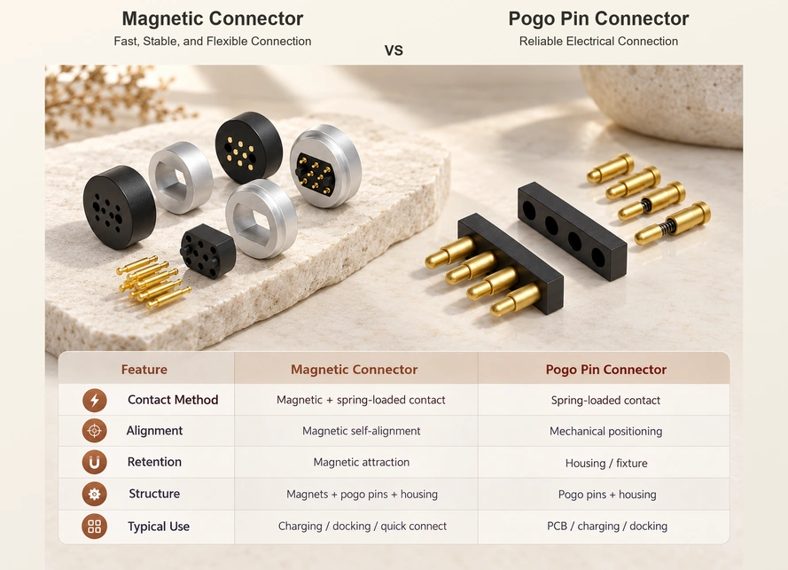
Magnets change the mating mechanics. Properly designed contacts in either version can carry power and signals, while magnetic capture may suit frequent docking, convenient alignment and quick disconnection.
DigiKey's introduction to pogo-pin connectors describes the plunger, barrel and spring arrangement for further structural background.
pogo pin connectorsHow Both Contact Systems Work
The enclosure, fixture, guides or other mechanical features position a standard interface. Its pins compress within the working stroke to provide the pressure needed for electrical continuity.
Video material pending replacement
In a magnetic interface, attraction helps capture the halves and the mechanical geometry sets their final position. The pins then compress against the pads. Magnetic force provides capture and retention, with physical contacts completing the circuit.
A magnetic cable connector assembly can combine that interface with USB-A, USB-C, bare-wire, terminal or other cable ends.
Magnetic Cable ConnectorAlignment and Retention
Guide pins, housings, chamfers, fixtures, clips and latches can position a standard pogo-pin connection. Magnetic capture can make the initial approach easier for frequent user connections without precise manual plug insertion.
pogo pin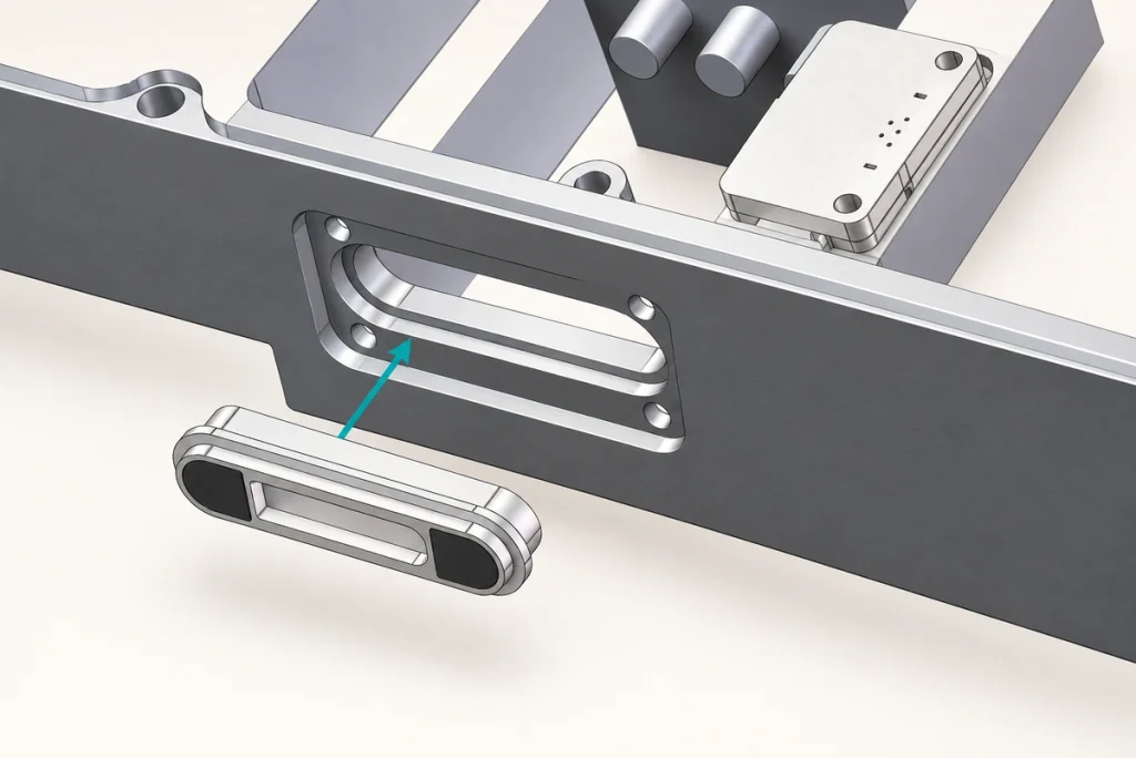
Housing geometry and mechanical datums still need to control the final X, Y and Z positions and the intended pin compression. Combine magnetic capture with these mechanical references for the completed mating position.
This approach can suit compact 4-pin interfaces used for charging, signals, docking or other external connections.
4 Pin Magnetic ConnectorWorking Stroke and Contact Stability
Both versions need adequate compression within the operating range. Too little may cause unstable contact or increased resistance; too much may increase spring stress and mechanical wear.
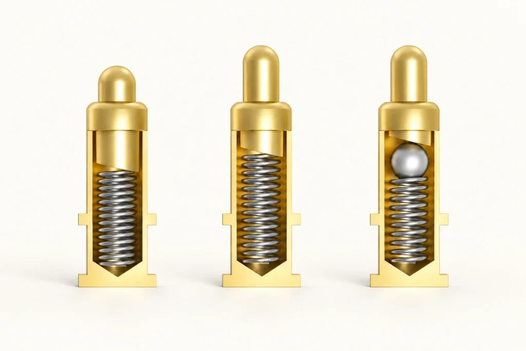
Magnetic retention adds a design variable. It must hold the intended mating position and pin compression during normal cable movement and handling. Review magnetic force with spring force, working height, geometry and release requirements; greater attraction is not always desirable.
Magtor 6-pin magnetic connector configurations list working stroke and magnetic force separately because each affects the mating system.
6 Pin Magnetic ConnectorDurability, Vibration and Breakaway
Both contact types can support repeated mating through spring movement rather than deep plug insertion. Actual life depends on pin design, plating, compression, mechanical guidance, cable loading and environment. The interface may still experience wiping and wear.
electrical contactSelecting magnetic holding force for the application can enable a detachable or breakaway interface for wearables, portable equipment, docks and suitable medical or handheld products. Vibration stability still requires whole-system evaluation; magnets alone cannot guarantee it.
| Comparison Factor | Standard Pogo-Pin Interface | Magnetic Pogo-Pin Interface |
|---|---|---|
| Electrical contact | Spring-loaded pogo pins | Spring-loaded pogo pins |
| Alignment | Housing, guide or fixture | Magnetic capture with mechanical guidance |
| Retention | Housing, latch, fixture or compression | Magnet-assisted holding force |
| Blind mating | Can be designed with guides | Capture may simplify the design |
| Quick release | Depends on the mechanical structure | Can be designed through holding-force selection |
| Breakaway function | Needs a specific release design | An available option requiring design validation |
| Working stroke | Needs controlled compression | Needs controlled compression |
| Magnet-attracted debris | No added magnet-specific risk | Needs assessment and management |
| System complexity | Often fewer magnetic design variables | Magnets add design inputs |
| Typical use | Internal or mechanically fixed contacts | Frequent external docking |
Scroll horizontally to view every column.
Design Trade-Offs When Adding Magnets
Magnets can help docking, one-handed use and compact breakaway design while reducing precise manual insertion. These features may be useful when a device is frequently connected and removed.
The added design inputs include polarity, holding force, orientation, nearby sensors, metallic debris, housing space, assembly process and cost. Exposed contacts also need an assessment of contamination, moisture and corrosion in their operating environment.
A 5-pin design can combine magnetic docking with power, signal, detection or control paths. Its magnet layout and contact assignments must still suit the device.
5 Pin Magnetic ConnectorChoosing for the Device's Requirements
A standard interface may suffice when a fixture, housing, latch or docking structure already controls compression reliably. Examples include internal PCB contacts, battery connections, test fixtures and modules mechanically secured after assembly.
Consider magnetic capture for frequent user docking, blind mating, quick release, compact external charging or detachable cables. Possible applications include wearables, docks, smart glasses, handheld electronics, portable instruments and compact medical devices.
Define current, signals, contact count, available space, stroke, magnetic force, mating cycles, cable direction, environment and user interaction before selecting the structure.
Matching the Mating System to the Product
Both interfaces rely on spring-loaded electrical contact. Standard designs mainly use mechanical positioning and retention; magnetic versions add capture and holding force to those mating functions.
Controlled mechanical compression may make a standard interface sufficient. Frequent docking, quick connection, blind mating or detachable external connections can benefit from magnetic assistance.
Adding magnets changes capture, mating and retention while the pogo pins continue to establish electrical contact through pressure against the mating surface.
Frequently Asked Questions
How does a magnetic pogo-pin interface differ from a standard one?
Both use spring-loaded contacts. The standard interface mainly relies on mechanical guides or fixtures, while magnetic capture assists alignment and retention in the magnetic version.
Does magnetic retention automatically improve reliability?
No. Review compression, working stroke, contact resistance, magnetic force, housing, plating and environment together. Magnetic capture can improve docking convenience, but the complete design determines contact performance.
Does adding magnets increase the contact's life?
Not by itself. Either type can be designed for repeated mating. Life depends on spring design, stroke, plating, pressure, contamination and operating conditions; spring movement still involves wear at the interface.
Can a standard pogo-pin interface support blind mating?
Yes, with housing geometry, guide pins, chamfers or fixtures that control alignment. Magnetic force is one way to aid the initial capture, rather than a requirement for blind mating.
When is magnetic capture worth considering?
Consider it for frequent docking, one-handed use, quick release, compact charging or detachable cables. Wearables, smart glasses, docks, medical equipment and portable electronics are possible applications, subject to their individual requirements.