
MLVision M5: Designing a Compact 2-Pin Magnetic Charging Interface
Published on September 16, 2026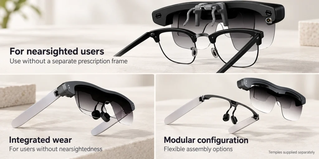
- The M5's Compact Interface Requirement
- A Two-Contact Charging Architecture
- Magnetic Connection in Daily Use
- Controlling Pogo-Pin Contact
- Designing for Repeated Mating
- Lessons for Smart-Glasses Development
For the lightweight MLVision M5 smart-glasses project, Magtor developed a compact two-contact magnetic charging interface. The project specifies DC 5V/1A, a 0.80 mm working stroke and a 10,000-cycle design requirement, combining magnetic positioning with spring-loaded contacts within a limited installation area.
MLVision M52 pin magnetic charging connectorThe M5's Compact Interface Requirement
Smart-glasses frames offer less internal space than smartphones, tablets and other handheld electronics. The charging interface must coexist with the battery, PCB, frame, display components and remaining electronics without unnecessarily enlarging the wearable.
The M5's stated product weight is 25.8 g. Its modular arrangement is intended to support a lightweight, comfortable pair of glasses.
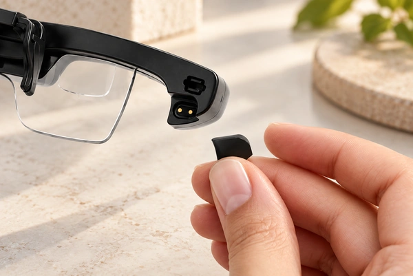
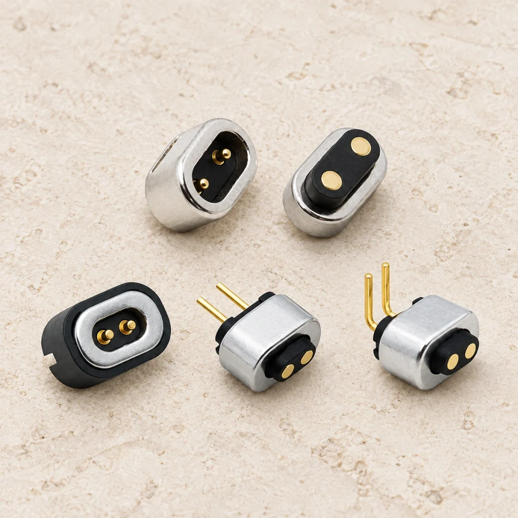
Magtor developed a small two-contact magnetic connector for this project. The project specification describes a front width of approximately 8.05 mm and a height of approximately 4.80 mm to fit the wearable's available space.
MagtorA surface-contact interface can occupy a small device area without requiring the same deep insertion arrangement as a recessed receptacle.
A Two-Contact Charging Architecture
This project's connector specification is DC 5V / 1A.
Where only positive and negative power paths are needed, two contacts keep the interface simple. Data, device identification, detection or control may require additional paths, depending on the system architecture.
One example of the charging path is:
USB power source → charging cable → 2-pin magnetic connector → smart-glasses charging circuit → battery.
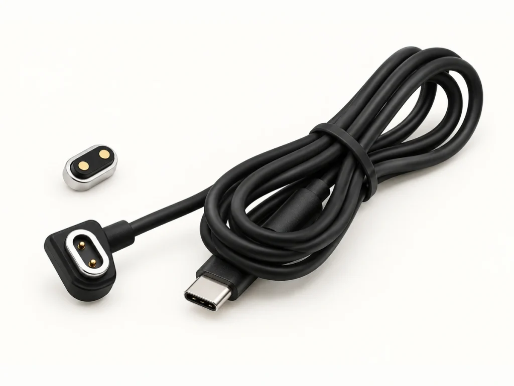
The magnets guide and retain the mating position; the pogo-pin contacts carry the electrical connection once the surfaces touch.
Magtor uses two-contact magnetic cables for suitable compact wearables that need charging only. Signal or detection requirements can lead to configurations with additional contacts.
Magtor 2-Pin Magnetic Charging Cable
Magtor 2-Pin Magnetic Charging CableMagnetic Connection in Daily Use
A conventional small plug must be aligned with its receptacle and inserted. On a lightweight wearable, that arrangement may need a larger housing opening and additional internal space.
The magnetic interface uses an approach-and-contact sequence.
As the charging head approaches, magnetic force helps guide it to the mating position. The spring-loaded pins then compress against their corresponding contacts to complete the electrical connection.
The connection sequence is:
Bring the cable close → magnetic alignment → pogo-pin contact → charging begins.
This describes a quick physical connection; it does not establish a fast-charging protocol.
The M5 interface is specified at 5V / 1A. Its discussed benefit is convenient, quick mating, without a claim of high-power fast-charging support.
A USB-C connector shape or magnetic coupling does not by itself provide USB PD or another fast-charging protocol. The Magtor two-contact cable documentation treats physical connection and protocol capability as separate design requirements.
USB-CUSB PDControlling Pogo-Pin Contact
The cable and device still need controlled mechanical contact. Magnetic attraction by itself cannot establish a stable electrical path.
At the specified 0.80 mm working stroke, the project lists a contact force of 60g ±20g per pin. Maximum spring travel is 1.0 mm; confirm the force-unit notation in the approved drawing.
Within the designed mating tolerances, spring travel accommodates small position differences while retaining pressure against the matching surface.
The specification sets a maximum contact resistance of 50 mΩ for each pin.
Size is only one selection input. Review:
Working stroke → contact force → working height → contact resistance → mechanical tolerance.
Insufficient compression can leave inconsistent contact, while compression beyond the specified range can shorten mechanical life. The project calls for operation within the designed working height.
Designing for Repeated Mating
Smart glasses may be connected and disconnected frequently, so mechanical durability belongs in the connector selection process.
The project specifies a 10,000-cycle life-test requirement. The test load, speed, environment and acceptance criteria need confirmation before this is represented as a passed result.
This interface avoids repeatedly inserting a rigid plug deep into the frame. Its pogo-pin plungers move mainly along the spring axis while the magnets assist positioning.
Review the following factors together:
Pogo-pin spring force, working stroke, magnetic polarity, magnetic force, contact surface, cable strain relief and connector housing dimensions.
For a smart-glasses OEM project, assess these factors during mechanical design, before the frame and PCB arrangement are finalized.
Magtor Magnetic Cable Connector
Magtor Magnetic Cable ConnectorMaterials and Surface Treatments in the M5 Specification
The project specification also lists materials and surface treatments.
It lists 0.125 μm gold plating on the pogo pins, an N52 NdFeB magnet with a Ni-Cu-Ni finish, and a black HTN insulating housing with a stated UL94 V-0 material classification. That material classification does not establish certification of the complete connector.
The same specification gives an operating range of -30°C to +60°C and a 24-hour salt-spray test requirement. The test method and acceptance conditions need confirmation.
Exposed wearable contacts can encounter skin moisture, sweat and other contamination in daily use, making the surface system an important design input.
For future projects with more demanding sweat-corrosion exposure, Magtor can evaluate alternative plating structures against the actual operating environment.
MLVision M5 Project Connector Specifications
| Project Item | Listed Specification or Requirement |
|---|---|
| Connector type | 2-pin magnetic connector |
| Rated voltage/current | DC 5V / 1A |
| Contact force at working stroke | 60g ±20g / pin |
| Working stroke | 0.80 mm |
| Maximum stroke | 1.0 mm |
| Maximum contact resistance | ≤50 mΩ / pin |
| Life-test requirement | 10,000 cycles |
| Operating temperature | -30°C to +60°C |
| Salt-spray test requirement | 24 hours |
| Pogo-pin plating | 0.125 μm Au |
| Magnet | N52 NdFeB |
| Magnet finish | Ni-Cu-Ni |
| Housing material/classification | Black HTN, UL94 V-0 |
Scroll horizontally to view every column.
These mechanical and electrical values are the project's listed engineering specifications, rather than independent measurements presented in this article.
Lessons for Smart-Glasses Development
The M5 case illustrates why the charging interface should be developed with the device, before it becomes an accessory chosen at the end of the layout process.
A connector only a few millimeters too large may interfere with the PCB, battery, hinge, speaker or frame. Choosing two contacts alone cannot resolve those installation constraints.
Before finalizing the connector, define installation space, voltage and current, PCB position, pogo-pin working height, mating direction, magnetic polarity, cable outlet direction and environmental requirements.
For charging-only smart glasses, a compact two-contact magnetic pogo-pin interface can minimize contacts. If communication, ID detection or other functions share the interface, assess whether additional contact paths are needed.
Coordinating the Interface with the Device
The 25.8 g MLVision M5 creates a compact wearable installation requirement. For this application, Magtor developed a two-contact charging connector specified at DC 5V / 1A, with N52 magnetic positioning and spring-loaded pogo pins.
The project brings connector dimensions, working stroke, contact force, current rating, magnetic structure and mechanical-life requirements into the same smart-glasses charging design.
For AI glasses, AR glasses and other compact wearables, Magtor can assess an interface using the device drawing, PCB arrangement and electrical requirements, then evaluate how the connector fits the available design space.