
Pogo-Pin Cycle Life: From Rated Cycles to Product Requirements
Published on September 15, 2026
- Typical Pogo-Pin Cycle Life
- What Counts as a Cycle?
- Why Cycle Ratings Differ
- Converting Cycles to a Usage Period
- Causes of Premature Wear
- Gold Plating and Service Life
- Designing for Longer Contact Life
- Magnetic Alignment and Wear
- Setting a Product's Cycle Requirement
Pogo-pin life is normally expressed as mating or compression cycles rather than calendar years. Depending on the design and operating conditions, a requirement may range from thousands of cycles to 100,000 or more. Stroke, spring force, plating, alignment, electrical load and environment all affect the result.
Typical Pogo-Pin Cycle Life
A single cycle target cannot describe every pogo-pin design.
Published specifications vary with contact construction and intended use. A moderately used connection and a frequently mated charging interface may need different durability targets.
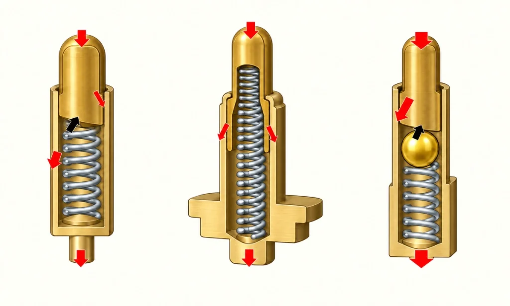
DigiKey's spring-contact category provides examples for frequently mated charging cradles and handheld equipment. Catalog durability values vary by part. A figure such as 100,000 cycles must be checked against the selected SKU and its stated test conditions; it is neither a category-wide limit nor a Magtor rating.
Spring-Loaded Pogo Pin Contacts — DigiKeyA useful selection question is:
How many cycles can this particular contact support under the product's operating conditions?
That is more useful than asking only:
How long do pogo pins last in general?
Define the required mating life together with working stroke, contact force, current, plating, mating-pad finish and exposure conditions.
What Counts as a Cycle?
A cycle commonly means one complete compression and release of the plunger. Confirm the exact definition used for the selected contact's durability test.
For a charging dock, the sequence is approximately:
The device is connected → the pin compresses → the device is removed → the pin releases.
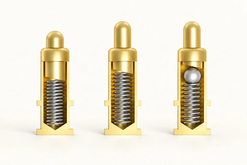
A pin that still moves after thousands of cycles has not necessarily retained a reliable electrical connection.
Durability must cover the required mechanical and electrical performance.
Evaluation can include contact-resistance stability, changes in spring force, smooth plunger movement and excessive surface wear.
EIA-364-09 is a connector durability procedure concerned with mating and unmating. Its DLA registry entry identifies the document; the applicable procedure and acceptance criteria still need to be obtained and specified for the project.
EIA-364-09 Connector Durability Test ProcedureA statement such as '50,000 cycles' is meaningful only when the test conditions and pass/fail criteria are known.
Why Cycle Ratings Differ
Contact life depends on the complete mating system, rather than on a single component in isolation.
Working Stroke
The operating stroke has a substantial effect on contact life.
Use the contact within its recommended compression range.
Too little compression can leave insufficient force and an unstable connection. Excessive compression can stress the spring, plunger, barrel, plating, PCB and housing.
The housing should establish the final mating position; the pogo pin should not serve as the enclosure's mechanical stop.
Contact Force
Provide enough contact pressure for the electrical requirement while controlling mechanical stress and wear.
Increasing spring force does not automatically improve reliability.
Additional pressure may improve contact in some conditions, but it can also increase wear on the tip and mating pad.
Select force with the number of contacts, product weight, magnetic attraction, vibration, device tolerances and contact-resistance requirement in mind.
Plating System
Each mating action applies pressure to the surface and may also cause a wiping movement.
Repeated interaction can wear the plated surface.
Gold can support a stable, corrosion-resistant contact surface. Its performance depends on thickness, hardness, the nickel barrier, contact pressure and mating-pad finish.
The guide to gold-plated pogo-pin connectors discusses the surface system in more detail.
Pogo Pin Gold Plating: Thickness, Wear & CorrosionAn appropriately thicker or harder finish may improve wear resistance, but cannot compensate for severe misalignment or over-compression.
Alignment
Pogo-pin plungers are primarily designed to move along their axis.
Sideways loading can make movement uneven, increase rubbing between the plunger and barrel, or drag the tip across the pad.
These conditions can accelerate mechanical and plating wear.
Housing geometry, guides and magnetic positioning can reduce uncontrolled lateral movement. Magnetic attraction still needs accurate mechanical positioning.
Operating Environment
Laboratory cycling does not represent every condition encountered in service.
A clean desktop cradle differs from a watch, hearing device, outdoor tracker or medical wearable. Sweat, humidity, skin oils, dust, cleaning agents and salt can change the contact's exposure.
Contamination can increase resistance, and corrosion may develop where the protective surface has been damaged.
See the guide to contact wear and corrosion for these interacting risks.
Preventing Charging Contact Corrosion in WearablesConverting Cycles to a Usage Period
Cycle counts can be converted into a cycle-equivalent usage period for an assumed daily mating frequency.
The calculation is:
Cycle-equivalent years = rated cycles ÷ cycles used per day ÷ 365.
The following examples illustrate that calculation:
| Usage Frequency | 10,000 Cycles | 50,000 Cycles | 100,000 Cycles |
|---|---|---|---|
| 1 cycle/day | 27.4 years | 137 years | 274 years |
| 2 cycles/day | 13.7 years | 68.5 years | 137 years |
| 10 cycles/day | 2.7 years | 13.7 years | 27.4 years |
| 50 cycles/day | 0.55 years | 2.7 years | 5.5 years |
| 100 cycles/day | 0.27 years | 1.37 years | 2.74 years |
Scroll horizontally to view every column.
These values are arithmetic conversions only.
For example, the 68.5-year result for 50,000 cycles at twice per day does not imply that the contact will remain serviceable for roughly 68 years.
Calendar life can also be limited by corrosion, plating wear, spring fatigue, contamination, vibration, temperature, electrical load, PCB-pad wear and damage elsewhere in the device.
Use the conversion to estimate a cycle requirement, rather than as a promise of calendar life or weather resistance.
A consumer device mated twice daily and a production fixture used hundreds of times during a work shift have very different cycle demands.
Causes of Premature Wear
A contact may wear sooner when its actual operating conditions are more demanding than the conditions represented by the specified cycle rating.
Mechanical stress can reduce spring force and leave insufficient contact pressure.
Compression and wiping can wear plating, especially when alignment is poor or force is excessive.
Once the surface is damaged, moisture and contamination may reach the underlying material more readily.
Contact resistance describes resistance at the interface between touching conductive surfaces. An increase can cause additional voltage drop and heating.
Contact Resistance OverviewFine dust, debris, dried sweat or other deposits around the plunger can cause sticking or inconsistent stroke.
Loading the pin at an angle rather than along its axis can concentrate wear on one side.
Operating beyond the applicable current range can increase heating, particularly when contact resistance has risen.
Cycle count alone does not explain every failure.
Consider cycling together with mechanical loading, surface condition, electrical load and environment.
Gold Plating and Service Life
Gold plating may help maintain contact performance, but does not establish a fixed cycle life by itself.
Evaluate the complete surface system.
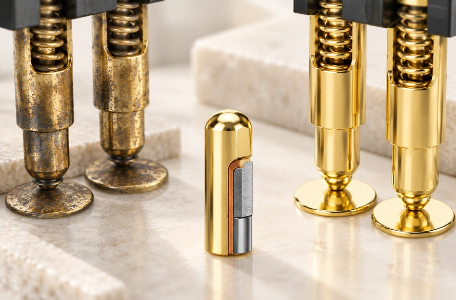
A typical stack uses a base material, a nickel barrier and a gold surface. Gold resists oxidation and supports contact stability, while the layers beneath it also contribute to performance.
The surface can still wear during repeated mating.
Exposed base material may face greater corrosion and resistance risks in humidity, salt or sweat.
Include the mating surface in the assessment.
Even a durable pin can be paired with an unsuitable PCB finish that wears first.
Assess these features together:
Pin plating + mating-pad finish + contact force + working stroke + alignment.
Treat them as one mating system, rather than judging the pin independently.
Designing for Longer Contact Life
Design the contact system for its intended operating conditions.
Use the recommended working stroke; avoid treating maximum compression as the normal operating position.
Where appropriate, provide an enclosure stop so manufacturing tolerances and user pressure do not cause excessive compression.
Choose enough force for repeatable contact without adding unnecessary mechanical load.
Control alignment through guides, housing geometry, mating-surface design and magnetic positioning.
Specify the expected cycles and exposure together. An indoor connection used only a few hundred times has different needs from a daily-worn device exposed to sweat.
Check current and contact resistance at the system level, since increased resistance can add voltage drop and heat.
A durability test should define stroke, load, alignment, environment, mating surface and electrical performance, rather than reporting cycle count alone.
Magnetic Alignment and Wear
Magnetic positioning can help when the magnetic and mechanical design are coordinated.
Magnets can guide the mating halves and reduce the need for manual insertion and positioning.
This can suit frequently connected wearables, charging docks, handheld equipment and similar products.
Magnetic attraction alone does not guarantee longer contact life.
If magnetic force pulls the halves together at an angle or the pins strike a pad edge, lateral wear can increase.
Coordinate magnetic force, pin position, working stroke, housing tolerances and pad geometry.
Explore the Magtor magnetic connector range and the magnetic pogo-pin connector selection guide for related configurations and design questions.
Magnetic Cable ConnectorHow to Choose a Magnetic Cable Connector for Your DeviceSetting a Product's Cycle Requirement
The highest advertised cycle count is not automatically the best selection.
Begin with the product's use pattern.
Estimate daily cycles and expected operating years, then consider moisture, vibration, dust, sweat and repeated shock.
Define both the electrical and mechanical requirements.
A watch docked once per day may have a modest cycle demand but significant corrosion exposure. An industrial fixture may operate in a cleaner environment yet mate dozens or hundreds of times each day.
Those products need different contact specifications.
Some listed Magtor 2-pin and 4-pin cable configurations specify durability of 10,000 or more mating cycles. Confirm the selected configuration, test conditions and report before relying on that figure; it does not apply automatically to every model.
2 Pin Magnetic Charging Cable4 Pin Magnetic Charging CableFor a custom Magtor configuration, review working height, stroke, force, pitch, plating, current, magnetic force, cable termination and environment together.
The magnetic connector range provides options for guided mating, repeated connection and compact interfaces.
Magtor Magnetic Connector seriesChoosing a Meaningful Durability Target
How long will a pogo pin last?
The answer depends on the selected part and how it is used.
Stroke, force, plating, alignment, mating surface, current, contamination, corrosion and environment all contribute.
A few thousand cycles may cover years of a low-frequency usage budget, without guaranteeing calendar life. A high-cycle contact can still wear quickly if it is over-compressed, misaligned, contaminated or operated beyond its electrical limits.
For a product designer, a more useful question than:
How many cycles is the contact rated for?
is:
Can the complete contact system maintain the required mechanical and electrical performance throughout the device's intended use?
Designing around that requirement helps connect durability targets with practical reliability checks.