
Choosing Magnetic Charging Cable Pin Count from Required Functions
Published on September 11, 2026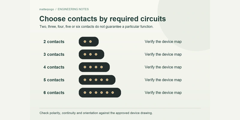
- Counting Required Electrical Paths
- Define Functions Before Contact Count
- Two Through Six Contacts: Design Examples
- Contact Count and Charging Performance
- Contact Count and Communication
- An OEM Selection Process
- Choosing a Practical Starting Configuration
Choose contact count from the electrical paths the device needs. Two may carry power and ground; three to six can add detection, ID, control or data paths where required. Extra contacts do not inherently increase charging speed.
Counting Required Electrical Paths
Provide enough conductive paths in the magnetic cable for the functions that cross between cable and device.
magnetic charging cableA basic rechargeable device may need only:
Power and ground.
Two contacts may therefore be sufficient for that design.
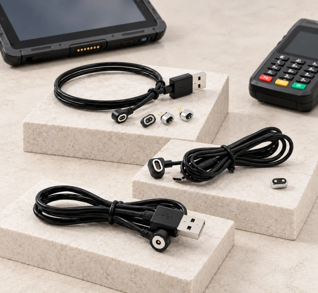
If a separate path is needed to detect charger connection, a third contact is one possible choice:
Power, ground and detection.
Signals, identification, control or communication may call for four, five, six or more contacts, depending on the architecture.
| Required Functions | Example Starting Pin Count |
|---|---|
| Power + Ground | 2 Pin |
| Power + Ground + Detection | 3 Pin |
| Power + Ground + 2 additional functions | 4 Pin |
| Power + Ground + 3 additional functions | 5 Pin |
| Power + Ground + 4 additional functions | 6 Pin |
Scroll horizontally to view every column.
These are starting examples. The device's electrical architecture determines the actual count and assignments.
Define Functions Before Contact Count
Choosing a connector before defining its functions can leave electrical requirements unaddressed.
For OEM development, define the required connections before selecting the structure.
List every function crossing the interface: power, ground, charger detection, device ID, control, sensing and communication as applicable.
Use that list to prepare a preliminary pin map.
For a hypothetical wearable, the required paths might be:
Power / ground / charger detection / device ID.
If these need four independent paths, a four-contact design is a possible starting point.
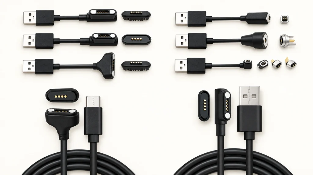
A different product may require charging alone:
Power / ground.
Unused extra contacts can add connector, conductor, PCB and assembly complexity without a needed function.
Build a contact budget by counting the required paths before choosing the number of physical contacts. That budget supports, rather than replaces, the actual wiring design.
Two Through Six Contacts: Design Examples
Different counts offer different scope for assigning independent paths.
They do not define fixed performance grades.
| Pin Count | Example Pin Assignment | Typical Design Requirement |
|---|---|---|
| 2 Pin | V+ / GND | Charging or DC power |
| 3 Pin | V+ / GND / Detect | Charging with detection or ID |
| 4 Pin | V+ / GND / Signal 1 / Signal 2 | Power with additional signals |
| 5 Pin | V+ / GND / Detect / ID / Signal | Multifunction device interface |
| 6 Pin | Power / Ground + multiple signals | More complex power and signal requirements |
Scroll horizontally to view every column.
Two Contacts
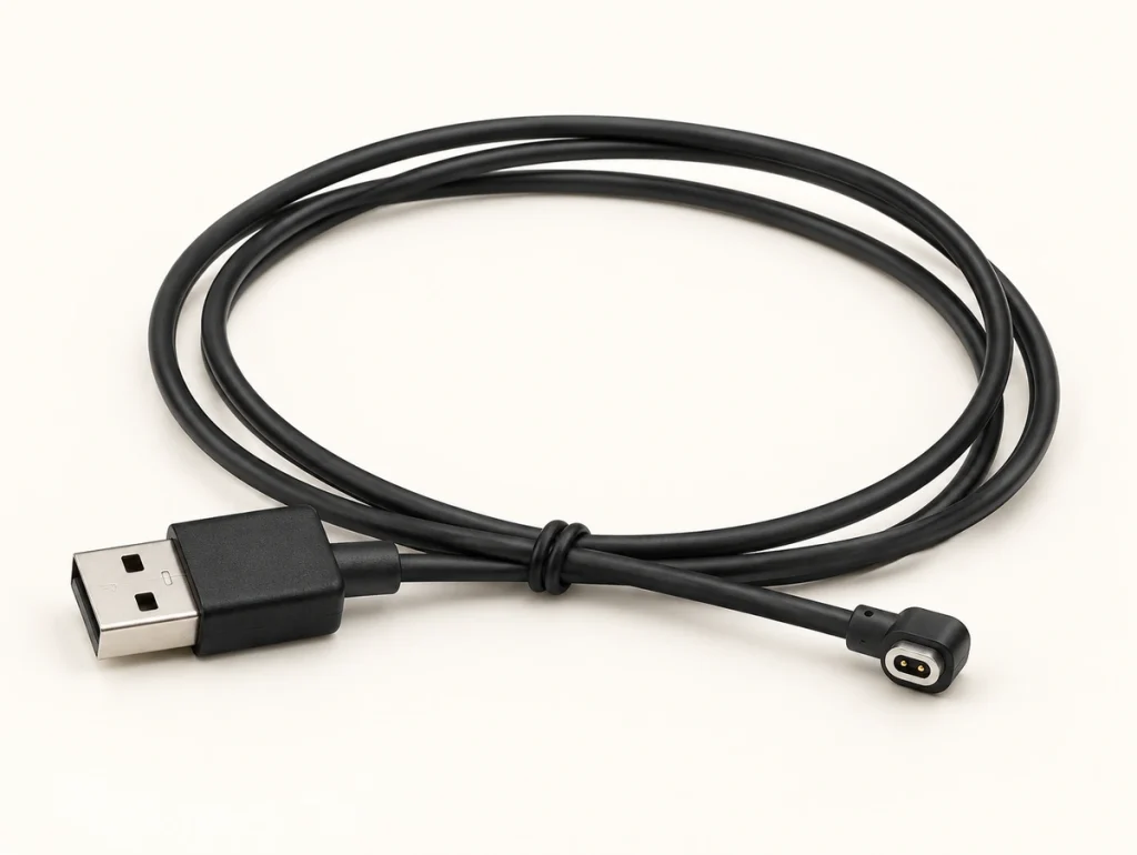
A two-contact cable can suit an interface needing positive power and ground.
Two ContactsThis can help fit charging into wearables, trackers, personal-care products, sensors and other compact equipment with limited interface space.
In a conventional independent-path design, two contacts leave little room for additional functions at that interface.
Three Contacts
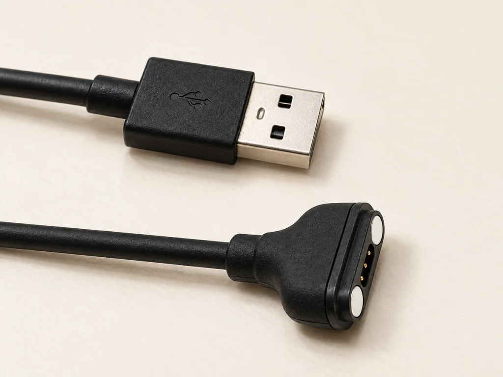
A three-contact cable provides one path beyond a basic power-and-ground pair.
Three ContactsThe circuit may assign it to charger detection, device identification, temperature sensing, control or another dedicated function.
Consider it where one additional path is needed but several separate signals are unnecessary.
Four Contacts
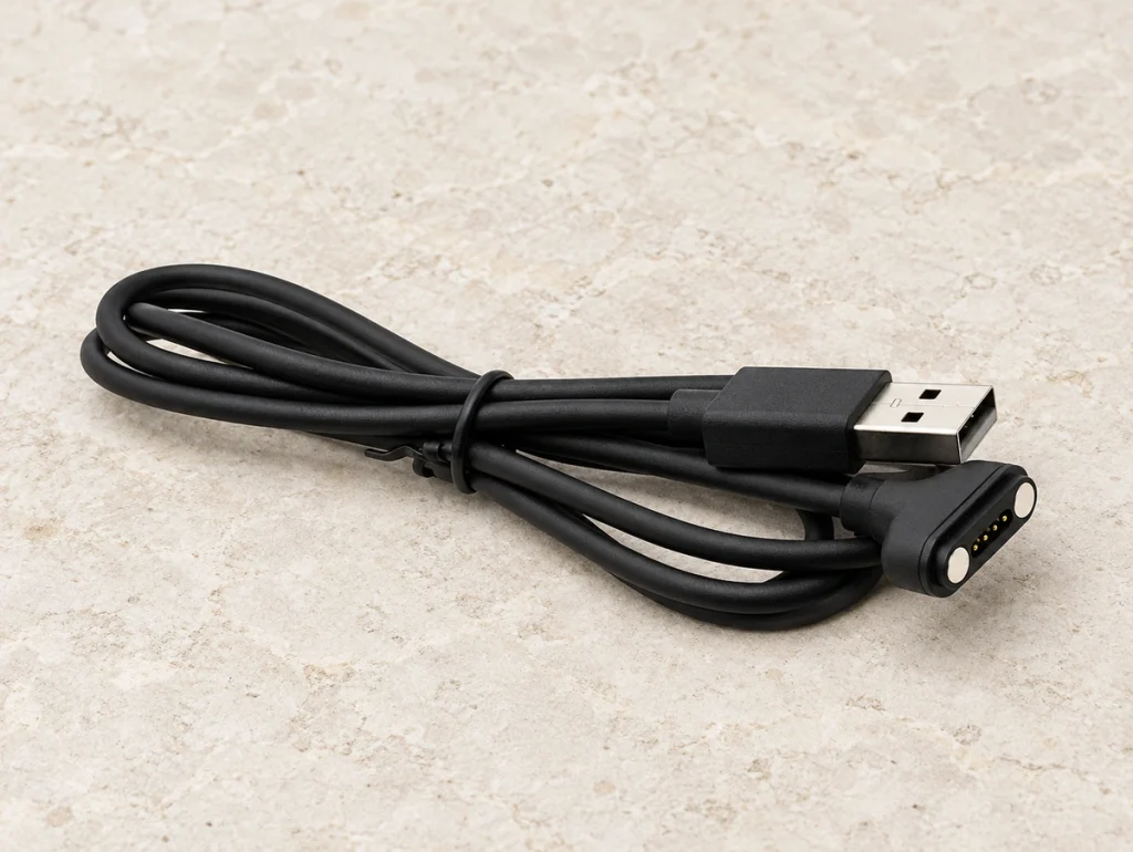
A four-contact cable adds two paths to the basic supply and ground pair.
Four ContactsOne example is:
Power / ground / signal 1 / signal 2.
An alternative is:
Power / ground / ID / detection.
Four contacts do not imply USB. Cable wiring, PCB circuitry and the assigned functions determine what the interface does.
Five Contacts
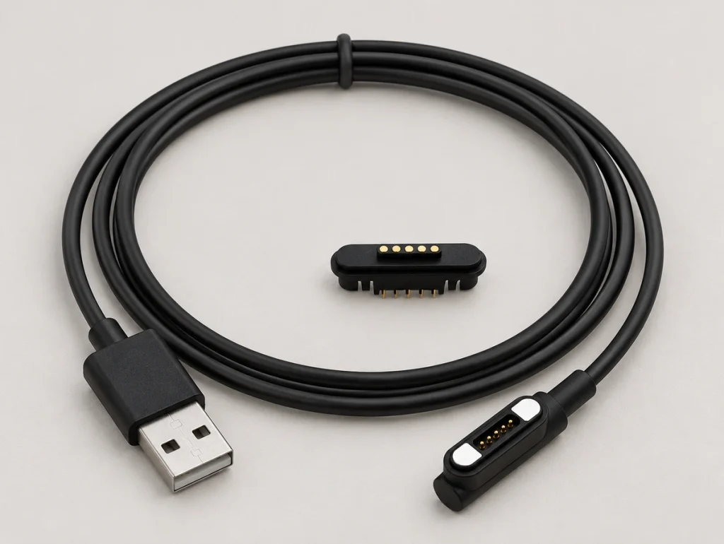
A five-contact cable adds room for combinations of charging, ID, detection, control or other signals.
Five ContactsFor example:
Power / ground / ID / detection / signal.
A fifth path may help where four contacts cannot carry the required functions without sharing a path or dropping a signal.
Six Contacts
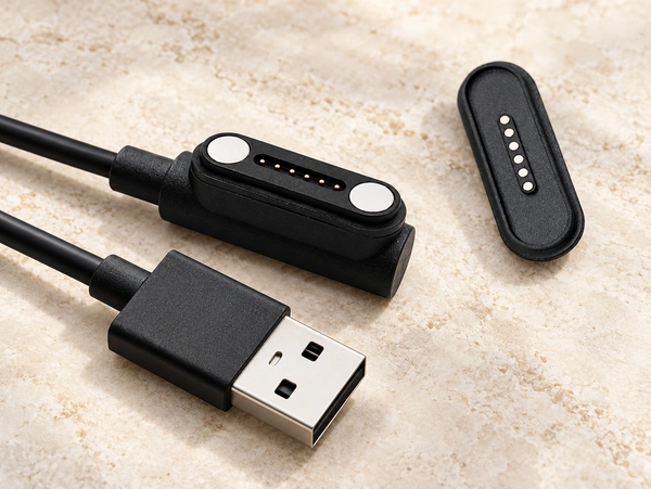
Six contacts may suit a compact interface requiring several separate electrical paths.
Assign them to multiple signals, control, sensing, identification or other device-specific functions as needed.
Use six where the architecture requires them. The added paths affect footprint, PCB routing, conductors and mechanical integration.
Contact Count and Charging Performance
Additional contacts do not automatically raise charging speed or current capacity.
Assess the whole path: contact design, resistance, pin dimensions, spring force, plating, conductor size, length, PCB traces and the device charging circuit influence performance.
A suitable two-contact power design could carry more current than a miniature six-contact interface intended mainly for signals. That comparison depends on the actual specifications.
Parallel supply or ground contacts are possible where needed, but deliberately design and validate current sharing and thermal behavior.
Do not choose four, five or six contacts solely to seek more charging power.
Set voltage and current first, then choose contact and conductor specifications.
Contact Count and Communication
More contacts alone cannot establish data capability.
The number gives available paths; electronics and protocol define their communication use.
One hypothetical four-contact map is:
Power / ground / Data+ / Data−.
Another four-contact map could be:
Power / ground / ID / detection.
The same count can thus serve different functions.
Five and six contacts follow the same principle. Additional paths do not automatically make an assembly USB, serial or another data interface.
Evaluate data capability across:
Assignments, cable wiring, contact characteristics, PCB design, communication circuitry and the device protocol.
A USB-C source end also proves neither USB data through the magnetic head, USB Power Delivery nor another fast-charging protocol. Confirm each intended function in the complete implementation.
USB-CUSB Power DeliveryAn OEM Selection Process
Select contact count within the full electrical and mechanical design.
Work through these steps:
Define voltage and current. Confirm power or charging needs before choosing the contact structure.
List every required function: power, ground, detection, ID, control, sensing, communication and reserved signals.
Create a preliminary map. Assign required paths and calculate the initial contact budget.
Check duplicated contacts. Additional ground or parallel supply paths may be needed, with their electrical behavior assessed.
Verify available space: width, pitch, PCB area, enclosure thickness, working height and cable outlet direction.
Review exposure: wearables and outdoor devices may need water protection, sweat and corrosion resistance, appropriate plating and repeated-mating validation.
water resistancePrototype the complete interface. Check polarity, resistance, temperature rise, magnetic alignment, continuity, mechanical tolerances and long-term mating behavior before production.
This process helps avoid unnecessary contacts as well as too few paths for the required functions.
Choosing a Practical Starting Configuration
Provide enough paths for the device while keeping the head and system as simple as practical.
| Device Requirement | Possible Starting Point |
|---|---|
| Basic charging or DC power | 2 Pin |
| Charging + one detection or ID function | 3 Pin |
| Charging + two additional electrical functions | 4 Pin |
| Charging + several ID, detection or signal functions | 5 Pin |
| More complex multifunction interface | 6 Pin |
Scroll horizontally to view every column.
Use the table as an initial design aid, not a wiring standard.
Equal counts do not establish compatibility. Pitch, electrical polarity, magnet polarity, dimensions, working height, assignments, voltage, current and internal wiring can all differ.
Check the final choice against the complete device design.
Magtor Magnetic Cable Connector configurations can vary count, end connectors, length, pitch, outlet direction, assignments and mechanical structure for OEM integration.
Begin selection with this question:
Which electrical functions must cross this device's magnetic interface?
That definition provides the basis for deciding contact count.
Define Functions, Then Validate the Assembly
Required electrical functions are the starting point for a magnetic cable's contact count.
Two paths may serve supply and ground. Three, four, five or six contacts can add detection, identification, signals, control or other functions according to the design.
Extra contacts do not inherently increase speed, current or data capability. Define functions, map and contact budget, then validate the complete interface's electrical, mechanical and environmental requirements.
Choosing from device requirements can reduce avoidable complexity and make OEM integration and validation more straightforward than selection by appearance alone.