
Defining the Pinout of a 4 Pin Magnetic Charging Cable
Published on September 10, 2026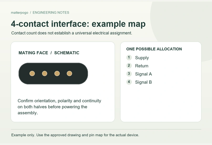
- Defining a Four-Contact Pinout
- Possible Contact Functions
- Checking Data Support
- USB-C and the Magnetic Contact Map
- Verifying Drawings and Orientation
- Different Wiring in Similar Heads
- Developing an OEM Pin Assignment
- Information for Cable Development
Four magnetic contacts can be assigned to power, ground, data, ID or control, but they do not define a universal pinout. Verify wiring, polarity, pitch and the complete device compatibility before connecting the cable.
4 pin magnetic charging cableSimilar-looking four-contact cables can still be electrically incompatible.
Defining a Four-Contact Pinout
A pinout records the electrical function of each connector contact.
The label 4 Pin identifies four available contact paths. It does not assign a function to Pin 1, Pin 2, Pin 3 or Pin 4 in a magnetic charging cable.
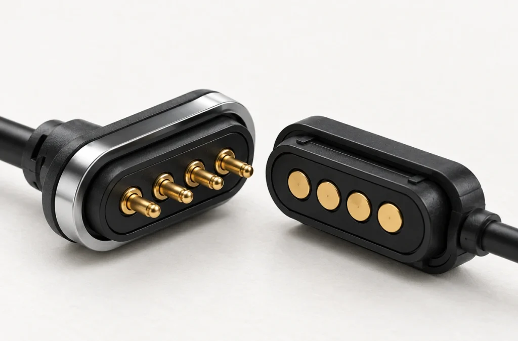
Magtor can define the map from the customer's PCB, charging circuit and device requirements instead of using one sequence for every four-contact assembly.
The 4 Pin Magnetic Charging Cable range shows available structures and configuration options.
4 Pin Magnetic Charging CablePossible Contact Functions
Power, ground and additional signals or control are possible assignments, with the configuration determined by the device.
Engineering examples include:
| Example Pinout | Pin 1 | Pin 2 | Pin 3 | Pin 4 |
|---|---|---|---|---|
| Charging + Detection | V+ | GND | ID | Detection |
| Power + Signal | V+ | GND | Signal 1 | Signal 2 |
| USB 2.0-style interface | VBUS | GND | D+ | D− |
| Higher-current design | V+ | V+ | GND | GND |
| Custom device interface | Power | Ground | Control | Reserved |
Scroll horizontally to view every column.
These arrangements illustrate design choices, rather than a universal standard.
Use the approved device schematic and cable drawing for final wiring.
Some four-contact products carry power and USB-related signals; others use the paths for charging and identification only. Confirm the particular design.
Checking Data Support
Four contacts alone cannot establish data support.
USB communication requires the intended wiring and complete electrical implementation.
A data-oriented cable might use:
Power + ground + D+ + D−.
That first arrangement includes the two data paths.
Those paths can serve USB 2.0 data when the complete system is designed for it.
USB 2.0 dataAn alternative charging-and-detection arrangement is power + ground + ID + detection.
That second configuration can provide charging and recognition without a USB data connection.
For example, a USB-C-to-four-contact assembly could leave its D+ and D− paths unconnected and be intended only for charging. Confirm this from the actual wiring rather than assuming a specific product has that configuration.
The practical reminder is:
Four contacts do not prove USB data capability.
Check the map and validate the required circuit, protocol and signal behavior before claiming data support.
USB-C and the Magnetic Contact Map
A Type-C source end does not assign the four magnetic contacts.
Type-C provides connections for VBUS, ground, Configuration Channel (CC), USB 2.0 D+ and D−, plus other signals where implemented. Their use at a custom magnetic interface must be designed explicitly.
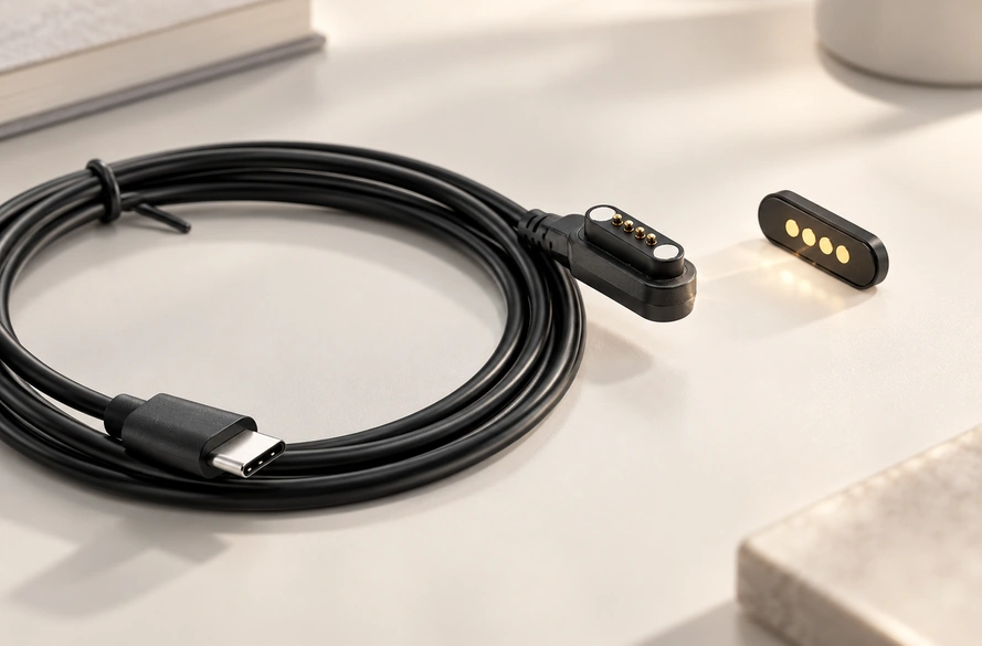
Choose which Type-C functions cross the magnetic head and implement the source-end control requirements accordingly.
One project-specific map could be:
USB-C VBUS → magnetic Pin 1; GND → Pin 2; D+ → Pin 3; D− → Pin 4.
A charging-only project may choose a different map.
Type-C does not establish USB Power Delivery on its own. Power capability depends on the complete implementation, control electronics, cable construction and connected devices.
Use USB-IF's Type-C cable and connector specification when defining Type-C requirements.
USB-IF USB Type-C specificationVerifying Drawings and Orientation
Confirm contact functions before connecting to a device, rather than choosing solely from the head's appearance.
An engineering drawing should state:
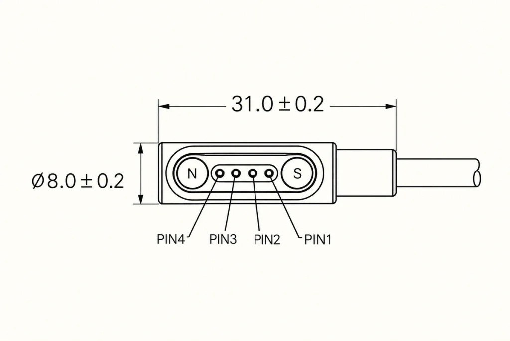
Pin 1 and viewing direction; V+ and GND positions; signal or ID functions; cable wire order; voltage and current needs; magnetic polarity; pitch and dimensions.
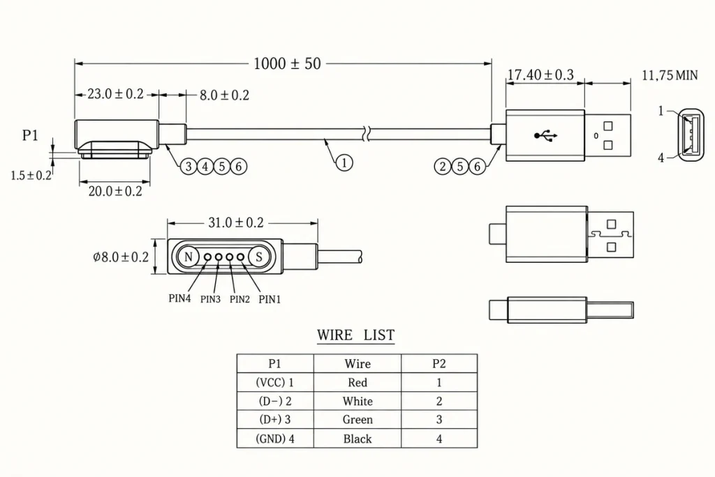
Viewing from the cable side instead of the mating device side can mirror the apparent sequence.
A map may then look correct on paper while reversing the physical contact order if the view is not labelled.
Verify electrical polarity against both the PCB schematic and connector drawing before applying power to a sample.
Different Wiring in Similar Heads
Yes, their assignments can differ.
Four contacts and similar dimensions still allow different electrical layouts.
For two hypothetical cables:
Cable A:
V+ / GND / D+ / D−
Cable B:
GND / V+ / ID / Signal
Interchanging them by contact count could deliver a signal or supply voltage to the wrong device pad.
Verify compatibility across the whole interface.
The checks include:
Assignments, polarity, pitch, dimensions, magnetic orientation, voltage and current, and signal requirements.
Evaluate the cable and device together instead of replacing a cable merely because its head looks similar.
The Magtor Magnetic Cable Connector range includes four-contact structures with different pitches, specified electrical requirements and terminations. Confirm the rating for the selected configuration; one specification cannot represent every layout.
Magnetic Cable ConnectorDeveloping an OEM Pin Assignment
Define required electrical functions first, then select a suitable mechanical structure.
Use the circuit requirements to answer:
What operating voltage is required?
What charging current must the interface carry?
Is data communication required?
Is ID or accessory detection needed?
Are other control signals needed?
Next define pitch, size, outlet direction and mating orientation for the mechanical interface.
A hypothetical wearable might assign:
Pin 1: V+; Pin 2: GND; Pin 3: charging detection; Pin 4: accessory ID.
An industrial design could instead assign:
Pin 1: power; Pin 2: ground; Pin 3: communication signal; Pin 4: control signal.
Match the head and wiring to the actual circuit. A search for a universal four-contact map cannot replace that definition.
Information for Cable Development
For a custom magnetic charging cable, prepare:
Device voltage and required current
Contact definitions or PCB schematic
Required pitch
Available installation space
USB-A, USB-C or bare-wire end
Length and conductor gauge
Required data, ID or control functions
Cable outlet direction
Magnetic retention needs
Environmental requirements, including water protection or corrosion resistance
After confirming these inputs, prepare the pin map and cable drawing before producing samples.
A Pin Map Defined by the Device
Four-contact magnetic cables have no universal pin assignment.
Power, ground, USB data, ID, detection or custom signals can use the paths when the design supports them. A USB-C end or four-contact appearance does not establish identical wiring or compatibility.
Before selection or manufacture, check assignments, polarity, electrical needs and mechanical fit against the device schematic.
Questions About Four-Contact Pinouts
Do all four-contact cables use the same polarity?
No. Verify V+, GND, signal and detection positions in the device schematic and approved wiring drawing; they may differ between designs.
Can a four-contact cable carry power and data together?
It can if the connector, conductors and device electronics support both. Four contacts alone do not establish USB data operation.
How is Pin 1 identified?
Use the connector drawing or PCB layout and its viewing direction. Opposite mating views can make the same physical sequence appear reversed.
Can another four-contact charger be substituted?
Only with matching electrical and mechanical requirements. Check assignments, polarity, pitch, dimensions, magnet orientation, voltage, current and required signals before replacement.
What details are needed for a custom assembly?
Provide voltage, current, contact definitions, pitch, dimensions, length, end connector, signals and installation space. A device drawing or PCB layout helps define the mating arrangement accurately.