
Designing and Selecting a 5 Pin Magnetic Charging Cable
Published on September 9, 2026
- The Five-Contact Cable Assembly
- Assigning the Five Paths
- Docking and Electrical Contact
- Power and Data Design Conditions
- An OEM Cable Selection Checklist
- Reliability of the Complete Assembly
- Typical Five-Contact Applications
A five-contact magnetic cable provides paths that can be assigned to power, data, identification or control. It has no universal pinout: match wiring, dimensions, magnet layout, voltage, current and the device connector before use.
5 pin magnetic charging cableThe Five-Contact Cable Assembly
The complete assembly has a device-side magnetic head with five conductive paths for power or signals. Its other end may be USB-A, USB-C, bare wire, terminals or another connector, selected for the device design.
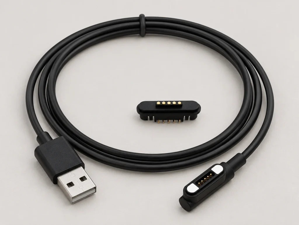
A head typically combines magnets with spring pins or fixed pads. Attraction helps align and retain the mating parts for charging or communication, but physical contact and a matched electrical layout are still required.
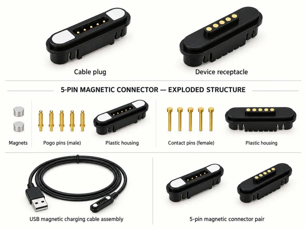
The cable assembly adds conductors, termination, strain relief, outlet direction and an external end connector to a standalone five-contact magnetic connector. Include all five in device integration.
5 pin magnetic connectorMagtor five-contact assemblies can use USB-A, USB-C or bare-wire ends with configurable length, pin mapping and 90° or 180° routing.
MagtorUSB-A, USB-CAssigning the Five Paths
The device circuit assigns the five contact functions; a magnetic cable is not required to follow one fixed five-pin arrangement.
Possible functions include power, ground, communication, identification and detection.
| Example Configuration | Possible Pin Functions |
|---|---|
| Charging + Detection | V+, GND, ID, Detection, Control |
| Power + Data | V+, GND, Data+, Data−, ID |
| Higher Current Design | 2 × V+, 2 × GND, Detection |
| Custom Device Interface | Power, Ground and 3 Custom Signals |
Scroll horizontally to view every column.
Nearly identical heads can therefore have different electrical assignments.
Specify the final map from the PCB, voltage and current needs, signal functions and approved wiring drawing. Record orientation and terminal numbering, because five contacts do not establish a universal pinout.
Approve that map before making prototypes instead of inferring it from contact count.
Docking and Electrical Contact
The interface combines mechanical alignment with conductive connection.
Magnets guide the mating parts together. Once aligned, pogo pins compress against matching pads within their working range to establish the conductive paths.
A typical sequence is:
Magnetic alignment → mating → pogo compression → electrical contact → power or signal transfer.
Guided docking can simplify repeated connection by reducing the need to insert a small plug precisely each time.
The specified pin travel can absorb small cable-to-housing dimensional variations within the permitted working and alignment range.
Power and Data Design Conditions
Five-contact assemblies can be designed for power and signals together. The contact count alone does not establish USB data support.
One example assigns two paths to power and ground, two to a differential signal and the fifth to ID or detection. A different circuit may assign all five differently; a differential pair is not necessarily USB.
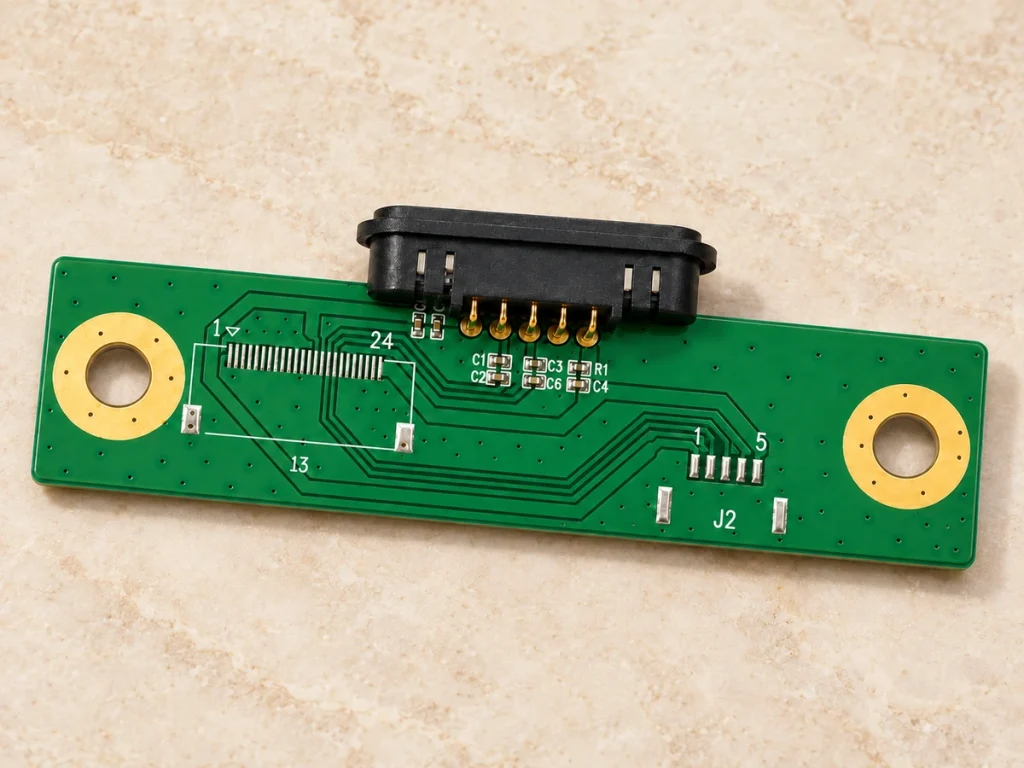
For signal reliability, assess:
Pin assignment
Cable conductor construction
Contact resistance
Cable length
Shielding
PCB routing
Signal requirements
A USB-C plug at one end leaves the same design questions at the magnetic head. It does not guarantee every USB function, transfer rate or power mode through five contacts.
USB-IF publishes Type-C cable and connector specifications covering their connector, cable, electrical and compliance requirements. Those standardized requirements remain separate from a custom magnetic pin map.
USB Type-CUSB-IFDefine the USB or custom signals that must cross the interface first, then design the contact map and cable construction for them.
An OEM Cable Selection Checklist
Checking for five contacts at both ends is only one part of selecting a cable.
First specify voltage, maximum current, assignments, charging needs, signal functions and acceptable resistance. When carrying power and data, also assess conductor arrangement and signal integrity.
Then check size, pitch, pin locations, magnet locations, mating height, working compression and outlet direction against the mechanical design.
Select the cable construction for the product as well, including:
USB-A, USB-C or bare-wire end; length; wire gauge; jacket material; 90° or 180° outlet; strain relief.
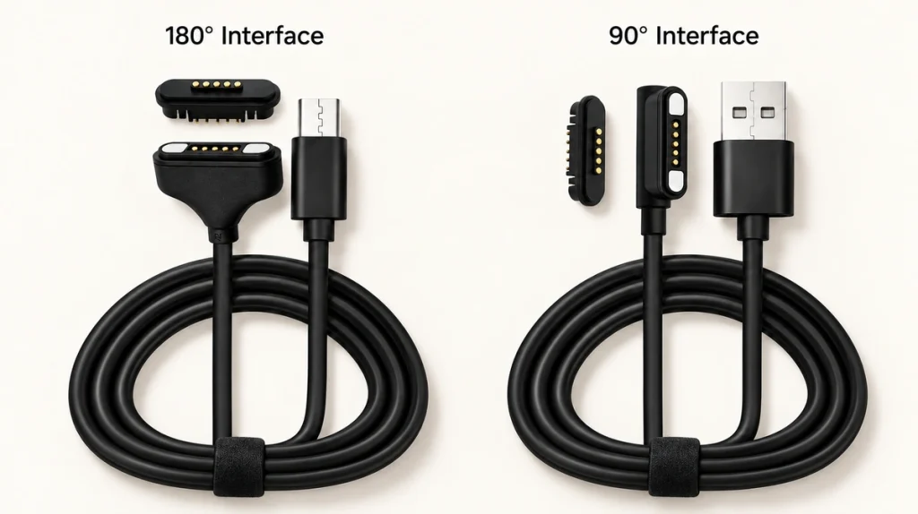
Wearable, medical, industrial and outdoor products may differ in moisture protection, sweat exposure, temperature, cycle demands, retention force and corrosion resistance.
Select a Magnetic Cable Connector within the whole product. Magtor can assess device-side geometry, conductor gauge, length, termination, retention force and environmental requirements for a configured assembly.
magnetic cable connectorReliability of the Complete Assembly
Long-term performance involves the magnetic head and every part of the cable assembly.
Specify and validate spring force that maintains contact through the required mating cycles. Assess the finish for wear, oxidation, moisture and contamination that may raise resistance over time.
Wearables repeatedly expose contacts to moisture, salts and skin deposits. A suitable gold or multilayer finish can be selected and validated for sweat and electrochemical corrosion resistance under those conditions.
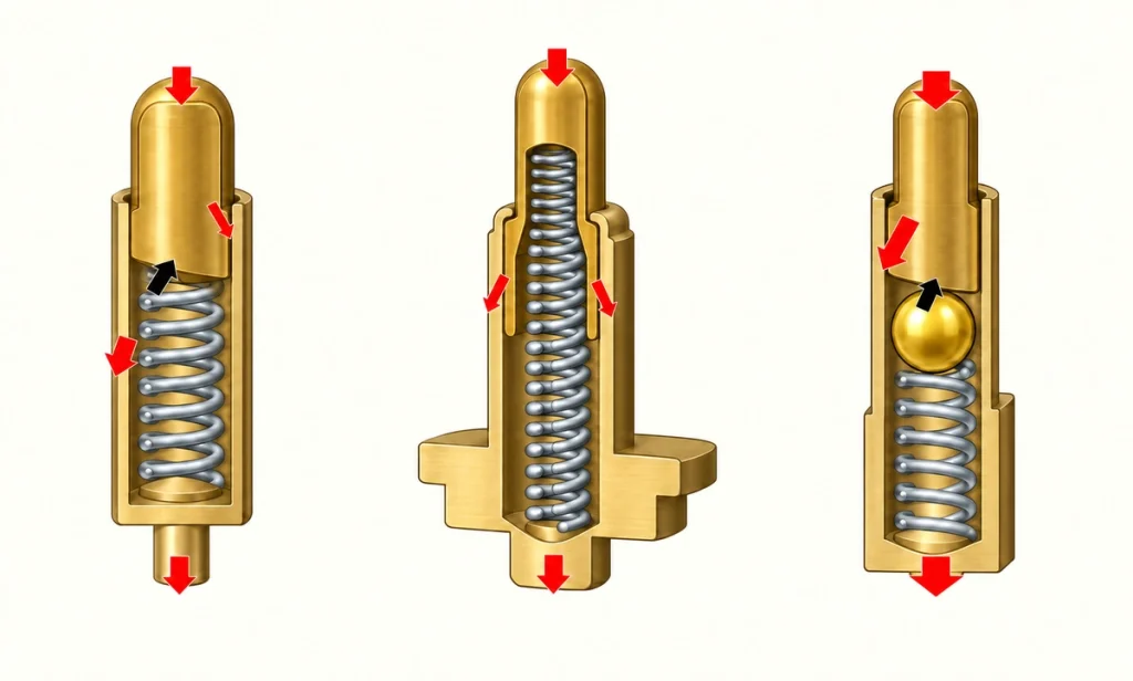
Also assess strain relief, magnet retention, housing strength, sealing, cable flexing and the mating quality between the head and device connector.
Evaluate behavior after repeated charging, bending and environmental exposure, as well as over the required life. Initial electrical readings alone do not establish cable durability.
Typical Five-Contact Applications
The extra paths can suit functions beyond simple two-wire charging when the device circuitry implements them.
Watches and wearables can assign paths to charging, detection, identification or communication. Select the contact finish for repeated sweat exposure where applicable.
Medical and healthcare electronics may benefit from compact docking for frequent charging or connection without repeated plug insertion, subject to the project's requirements.
Docks can use magnetic guidance for drop-in or blind mating, with alignment geometry and tolerances designed for that behavior.
Handheld and portable equipment can combine power with signals or detection. A suitably retained magnetic head can also release more readily than a tightly held plug.
Smart-home products may assign the contacts to power, control, identification or low-speed communication.
Industrial and sensor equipment can use a custom five-contact layout for power plus several dedicated signals in a compact interface.
Define the configuration for its application instead of choosing from contact count alone.
Specifying the Complete Five-Contact Interface
The five conductive paths in a magnetically guided cable can be assigned to power, ground, data, identification, detection or other custom functions according to the device.
No universal five-pin arrangement guarantees compatibility. Verify the map, voltage, current, dimensions, magnet layout, cable construction, device-side contacts and environment before selecting the assembly.
For an OEM design, configure USB-A, USB-C, bare-wire or another end with the required length, routing, assignments, retention and finish.
Questions About Five-Contact Cables
Are five-contact magnetic cables interchangeable?
Not by count alone. Match pitch, dimensions, magnetic polarity, assignments, voltage, current and the device-side layout.
Is there a universal five-pin magnetic pinout?
No. Five contacts supply five paths; the circuit assigns power, ground, data, ID, detection or another signal as needed.
Can the source end use USB-C?
Yes, but cable wiring, the contact map, device electronics and the USB implementation determine which functions reach the magnetic interface.
Can five contacts carry data?
They can where the connector and cable are designed for the signals. Assess assignment, conductor layout, length, resistance, shielding and signal requirements together.
What should an OEM provide for a custom cable?
Provide voltage, current, functions, dimensions, pitch, magnetic requirements, length, gauge, end connector, outlet direction, water protection needs and the operating environment.