
Magnetic Charging Cable Limitations to Consider
Published on September 3, 2026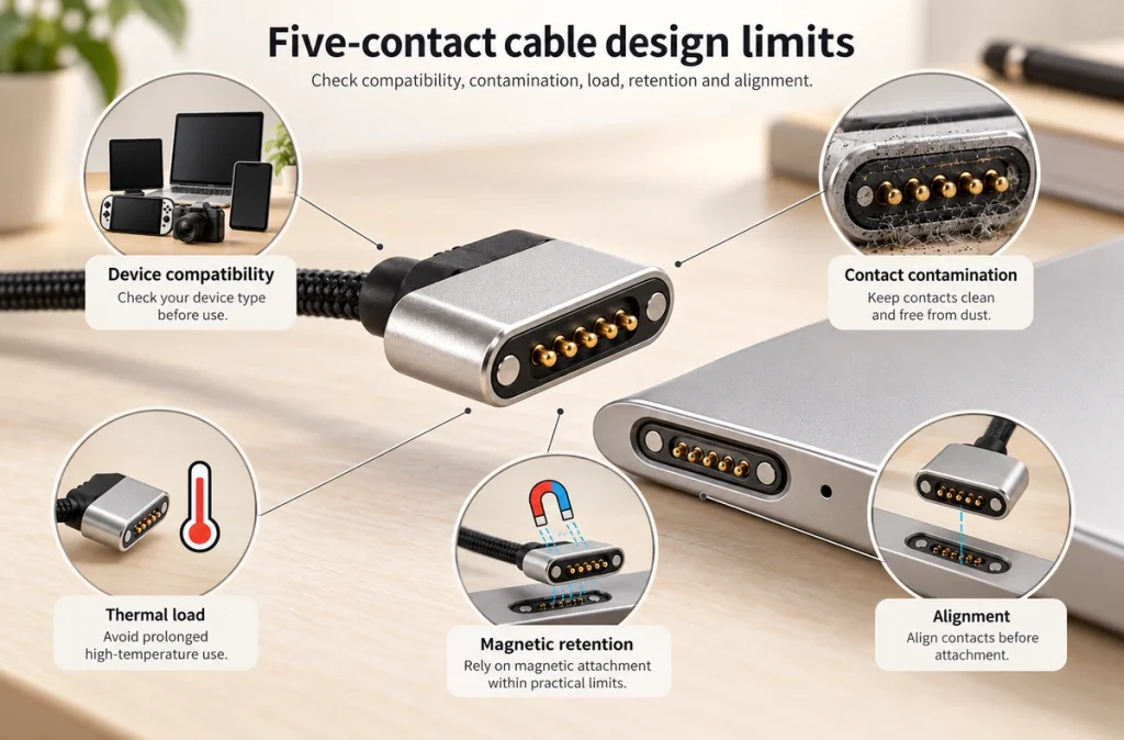
- The Main Limitations
- Device-Specific Compatibility
- Contamination on Exposed Contacts
- Contact Resistance at Higher Current
- Balancing Magnetic Retention and Alignment
- Checking Data Capability
- Choosing an Interface for the Application
Magnetic cables can simplify alignment and connection, but their suitability depends on the application. Assess device compatibility, contamination of exposed contacts, contact resistance, magnetic retention requirements and the data limits of the particular design.
The Main Limitations
Many magnetic charging interfaces are specific to a device, whereas USB-C has standardized connector requirements. A magnetic assembly's dimensions, pitch, electrical polarity, voltage, current, retention force and contact assignments can differ between products.
A similar-looking magnetic charger may therefore be unsuitable for the device.
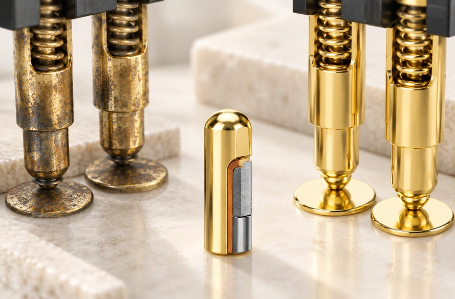
Other risks include dirty exposed contacts, voltage drop under higher loads, unintended separation with insufficient magnetic retention, and restrictions on signals or data.
For an OEM design, establish the electrical and mechanical requirements before choosing or developing the cable. This provides a basis for reducing these risks.
Device-Specific Compatibility
Compatibility deserves particular attention when selecting a magnetic cable.
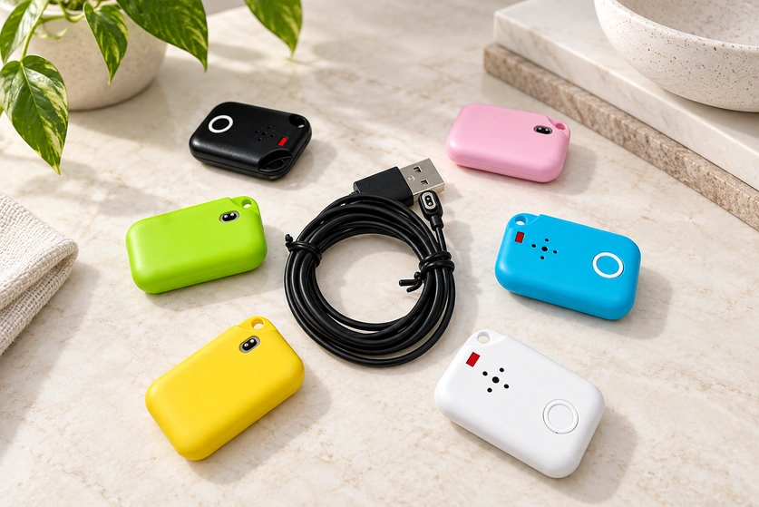
The labels 2 pin, 4 pin and 5 pin specify contact count, not a universal pinout. Two four-contact cables can differ in spacing, electrical polarity, voltage, magnet orientation and signal assignments.
Two contacts commonly carry V+ and GND. Extra contacts in a four- or five-contact design can serve signals, device detection or other circuit functions; the device schematic determines those assignments.
USB Type-C follows a standardized framework maintained by USB-IF. Its Cable and Connector Specification addresses plugs, receptacles, cables, orientation and related connection requirements.
USB Type-C Cable and Connector SpecificationBefore approving a device-specific cable, check pitch, pinout, voltage, current, electrical polarity, connector dimensions and the pogo pins' working height.
The Magtor Magnetic Cable Connector range can be configured for the device's requirements. It should not be treated as a single magnetic interface that fits every product.
Magnetic Cable ConnectorContamination on Exposed Contacts
Exposed pogo pins or pads can make docking straightforward, but they leave the contact surfaces more accessible to the surrounding environment.
Dust, moisture, sweat, oil and small metal particles can collect near the interface. Magnets can attract ferromagnetic debris, so workshops, outdoor equipment, wearables and other demanding settings need particular consideration.
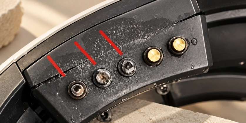
Deposits may restrict pogo pin compression or raise contact resistance, making charging intermittent.
Review plating, contact spacing, sealing structures, housing geometry and cleaning procedures to control contamination. A connector integrated into an appropriately validated IP-rated structure may suit wet or dusty equipment better than an open consumer interface; the complete assembly determines its protection.
Contact Resistance at Higher Current
The magnetic interface introduces a conductive junction between the source and device. That junction, like other contacts, has electrical resistance.
At a low load, its effect may be small. Higher current makes excessive contact resistance more consequential because it increases voltage drop and dissipated heat.
A magnetic cable is not inherently slow. Contact area, spring force, plating, wire gauge, cable length, cleanliness and the device's charging circuit together influence performance.
Specify the required current before selecting a cable instead of judging its electrical capability from the connector's appearance.
The Magtor 2 Pin Magnetic Charging Cable guide considers contact current rating, resistance, conductor gauge, cable length and the device charging circuit. A USB-C end alone establishes neither USB Power Delivery nor another fast-charging protocol.
2 Pin Magnetic Charging Cable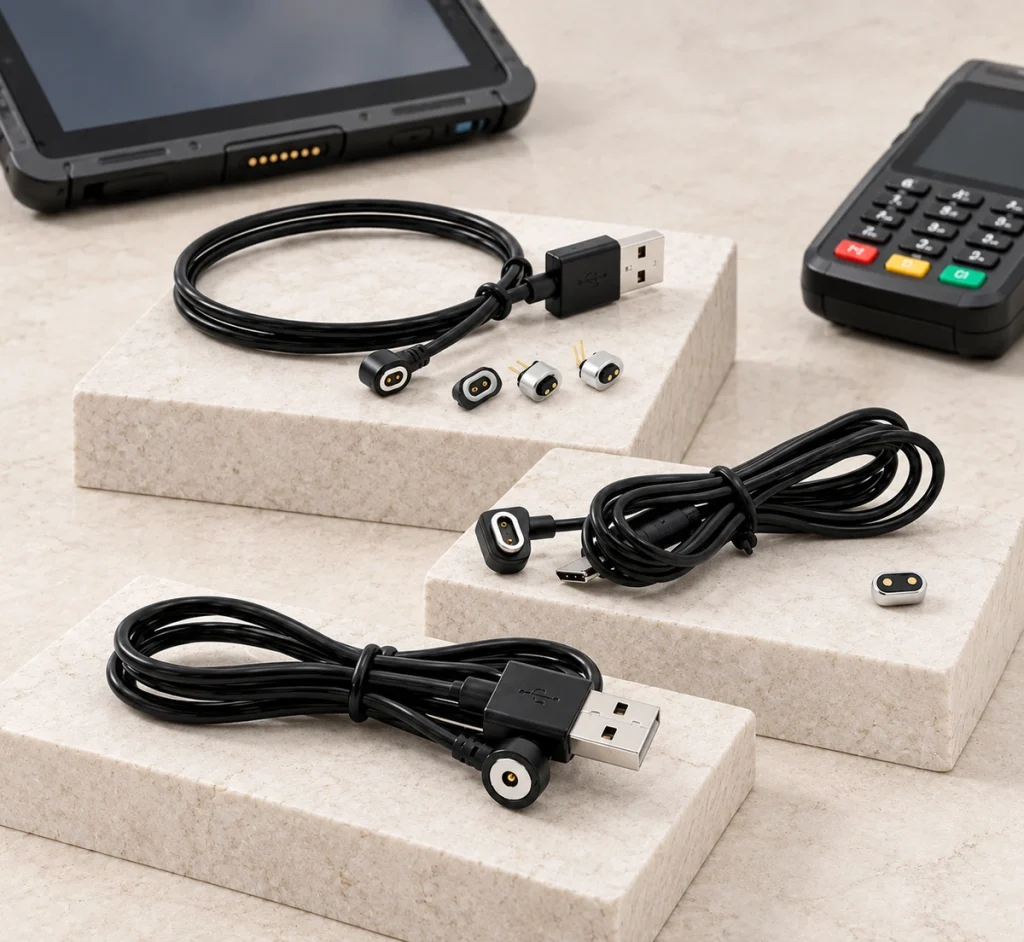
USB-IF's Cables and Connectors Guidance also distinguishes cable capabilities and advises selecting a cable for the intended USB environment.
USB-IF Cables and Connectors GuidanceBalancing Magnetic Retention and Alignment
Useful magnetic retention does not mean maximizing attraction in every design.
Insufficient attraction may allow cable weight, vibration or movement to separate the parts. Excessive attraction can make removal difficult and pass additional mechanical load into the housing.
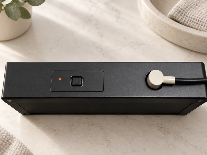
Coordinate magnetic retention with the pogo pins' spring force. Attraction must maintain engagement while the pins remain within their specified working stroke.
Assess attraction alongside these mechanical factors:
Connector dimensions and weight
Cable routing direction
Device mounting angle
Pogo pin spring force
Expected vibration
Enclosure construction
A 90° outlet may help where a compact device has little rear clearance; a 180° outlet can suit a straight cable route. The Magtor 4 Pin Magnetic Charging Cable range includes both arrangements for different enclosure and PCB layouts.
4 Pin Magnetic Charging CableChecking Data Capability
Additional contacts create possible electrical paths; they do not establish a data link by themselves.
Two-contact magnetic cables are commonly assigned to power and ground. Four-, five- and six-contact designs provide more paths, but the pinout and device electronics determine what those paths do.
Additional contacts can be assigned to:
Data or communication paths
ID detection
Charging control
Sensing
Additional power or ground connections
Four contacts therefore do not necessarily implement a four-wire USB connection.
When charging and communication share the interface, specify the protocol, signal layout, current, shielding needs and cable construction before choosing the connector.
Magtor magnetic cable assemblies can be configured for power, charging, signals and ID detection, with USB-A, USB-C, terminal-wire or custom ends. Explore the Magnetic Cable Connector options for the intended arrangement.
Explore Magnetic Cable Connector OptionsChoosing an Interface for the Application
Whether a magnetic cable, USB-C or another connector fits best depends on the device's requirements.
| Device requirement | Magnetic charging cable assessment |
|---|---|
| Frequent charging or docking | Potentially suitable with a matched design |
| Blind-mating connection | Potentially suitable with controlled alignment |
| Compact wearable device | Potentially suitable within the available space |
| Quick break-away connection | Potentially suitable with balanced retention |
| Custom power + signal interface | Potentially suitable with defined pin functions |
| Universal replacement cable required | USB-C may be more appropriate |
| Environment with heavy metal debris | Additional protection required |
| High-current charging | Careful electrical design required |
| High-speed standardized data | Assess the complete interface carefully |
Scroll horizontally to view every column.
USB-C will often suit priorities such as standardized accessories, broadly available replacements and established USB data functions, provided the chosen system and cable support them.
Consider a magnetic interface for frequent docking, guided alignment, quick release, custom assignments, compact packaging or device-specific power and signal paths.
Compare specifications when the choice is uncertain. The Magtor Magnetic Cable Connector Selection Guide covers contact count, current, voltage, signals, wire gauge, retention force, cable direction and the operating environment.
Magnetic Cable Connector Selection GuideDesigning Around the Limitations
The principal limits concern compatibility, exposed-contact contamination, contact resistance, magnetic retention design and the data functions available in the assembly.
These limitations still leave useful applications in wearables, handheld electronics, charging docks, smart devices and frequently connected equipment. In a suitable design, automatic alignment and less mechanical plugging can justify the trade-offs.
Develop the cable as part of the device's electrical and mechanical system. Match pinout, current rating, contact structure, magnetic force, routing and environmental protection to improve reliability rather than assuming a universal replacement.
Questions About Magnetic Cable Limitations
Can a magnetic cable be used for daily charging?
It can, if the design matches the device's voltage, current, pinout and operating environment. Keep contacts clean in accordance with device instructions, because moisture and metal debris can impair electrical performance.
What can cause intermittent charging?
Possible causes are dirty contacts, inadequate pogo pin compression, insufficient attraction, cable damage, or incorrect voltage and pin assignments. Check alignment and clean the disconnected interface according to the device instructions to help narrow down the cause.
Is magnetic charging necessarily slower than USB-C?
No. Compare resistance, current rating, wire gauge, length, charging protocol and the device circuit. A properly designed magnetic assembly can provide stable charging within its defined electrical limits.
Can a magnetic interface cause port damage?
A matched design can reduce repeated plug-in motion. Incorrect assignments, unsuitable voltage, contamination or poor connector design can still cause electrical or mechanical faults.
What determines a magnetic cable's service life?
Pin quality, plating, spring force, cable strain, contamination, current and docking-cycle count all matter. For an industrial or OEM product, define and validate the durability target during development.