
USB-A or USB-C: Choosing for Power, Data and Device Design
Published on September 1, 2026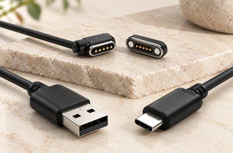
- Physical Differences Between USB-A and USB-C
- Comparing Connector Features
- Charging Power and Protocols
- Specifying Data Performance
- Connecting USB-A Equipment to USB-C
- Choosing for the Product's Ecosystem
- USB Source Ends for Magnetic Cables
- Matching the Interface to the Application
The two formats differ in physical design and in the power, data and accessory ecosystems used with them. USB-A remains common in existing equipment, while USB-C enables newer power and data implementations. This guide compares their use and the requirements that determine which connector suits a device.
Physical Differences Between USB-A and USB-C
Connector shape is the first visible distinction between the two formats.
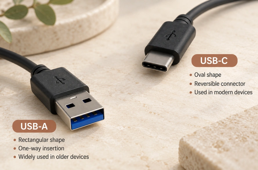
USB-A is the rectangular, single-orientation plug used for years on computers, wall chargers, power banks, industrial products and peripherals.
USB-C is smaller and rounded, with a reversible plug that can be inserted either way. This can simplify connection in compact portable products.
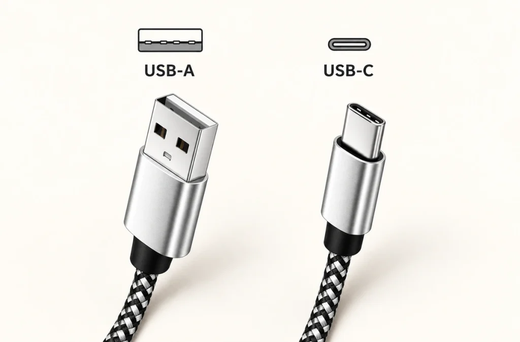
USB-IF's USB Type-C® Cable and Connector Specification describes a connector developed in part for smaller, thinner devices, with reversible insertion to improve usability.
USB Type-C® Cable and Connector SpecificationUSB-A and USB-C name connector formats, rather than specifying a fixed data rate.
A USB-C product may implement USB 2.0, USB 3.2, USB4, USB Power Delivery or other functions. Its design determines which are supported.
USB Power DeliveryThe practical implication is:
USB-C enables a higher potential performance ceiling, but a particular USB-C cable can still be slower than a particular USB-A cable.
Comparing Connector Features
The following comparison summarizes the main design and usability differences:
| Feature | USB-A | USB-C |
|---|---|---|
| Connector shape | Rectangular | Small, rounded |
| Plug orientation | One direction | Reversible |
| Size | Larger | More compact |
| Common applications | PCs, chargers, peripherals, legacy equipment | Phones, tablets, laptops, portable electronics |
| USB Power Delivery | Limited compared with modern USB-C implementations | Supports USB PD when properly implemented |
| USB4 support | No | Possible with a compatible USB4 implementation |
| High-speed data potential | Depends on USB version | Supports newer high-speed USB standards when implemented |
| Cable configurations | USB-A to USB-C/device connector; USB-A-to-USB-A requires an explicitly specified application | USB-C to USB-C/device connector |
| Magnetic charging cable use | Available | Available |
Scroll horizontally to view every column.
USB-A's established equipment base remains a practical advantage.
Many existing chargers, computers, adapters, docks and industrial products have USB-A ports. Devices intended to use that equipment can therefore still benefit from USB-A.
For a newly designed compact product, USB-C can bring charging, data and other implemented functions into one connector ecosystem.
Charging Power and Protocols
A common charging question is:
Will a USB-C connection charge the product faster?
It may support substantially higher power, but USB-C by itself does not establish a fast-charging capability.
Charging performance depends on these parts working together:
Power adapter
Cable
USB interface
Charging protocol
Device power-management system
USB Power Delivery is one important part of current USB-C charging systems.
USB-IF describes USB Power Delivery support up to 240W when the Type-C cable, connector, source and device meet the compatible-system requirements.
Appropriate USB-C implementations can therefore serve products from small consumer electronics to tablets and laptops.
A USB-C port alone does not demonstrate support for 60W, 100W, 140W or 240W charging.
A cable powering a small wearable, for instance, may provide only the voltage and current that the wearable needs.
Keep this distinction in view when specifying a custom charging cable.
A magnetic cable may use USB-C at its source end and only two power-and-ground contacts at the product. Its full electrical system sets the available capability; the source plug's appearance does not.
Specifying Data Performance
The USB-C shape is also not proof of faster data transfer.
Specify the USB data implementation separately from the connector format.
A Type-C cable can implement basic USB 2.0 functions. USB-IF notes that a USB 2.0 Type-C cable does not carry USB 3.2 or USB4 signals and operates at USB 2.0 performance levels.
USB 3.2USB4 uses USB Type-C and supports up to 80 Gbps in suitable implementations using compatible equipment and certified cables.
USB4Compare the actual supported USB specifications when assessing data speed, rather than rely on the plug outline.
A connector-format check might ask:
“Does it use a USB-C connector?”
For the application, also ask:
“Which data rate, protocol, pin layout and cable architecture does this product require?”
A charging-only product may gain little from adding high-speed USB data paths.
When charging and communication are both required, design the cable and contacts for the necessary power and data paths.
Connecting USB-A Equipment to USB-C
Their different shapes prevent a USB-A plug and USB-C receptacle from mating directly.
A correctly designed USB-A-to-USB-C cable or compatible adapter can link equipment using the two formats.
One example of such a connection is:
USB-A charger → USB-A-to-USB-C cable → USB-C device.
This can connect a newer USB-C device to an existing USB-A power source.
An adapter does not automatically add power or data functions that the connected equipment lacks.
Available charging power and data speed follow the mutually supported capabilities of:
Host + charger + cable + adapter + device.
USB-IF's USB4 guidance likewise describes compatible connections operating according to the equipment's shared capabilities.
Check whether the connectors can mate and whether the system meets the electrical requirements as separate questions.
Choosing for the Product's Ecosystem
The product's requirements determine which format is suitable.
USB-A remains useful where the product must work with installed chargers, computers, industrial equipment, stations or accessories.
Possible applications for USB-A include:
Charging docks, existing 5V adapters, desktop accessories, industrial products, test equipment and devices built around legacy USB supplies.
USB-C may suit new compact electronics where reversibility, small size or modern charging-ecosystem compatibility is important.
Examples of this product range include:
Smartphones, tablets, laptops, wearables, smart products, portable electronics and other newer consumer devices.
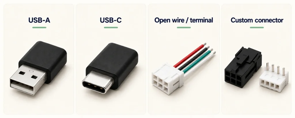
The two cable ends do not have to use the same connector format.
A custom device can use either of these arrangements:
USB-A → cable → custom device connector.
Alternatively:
USB-C → cable → custom device connector.
These layouts can help when a standard receptacle is too large, too deep or inconvenient for the enclosure.
USB Source Ends for Magnetic Cables
A compact product can also use USB-A or USB-C at the source and a magnetic connector at the device.
magnetic connectorThe first example is:
USB-A → cable → magnetic pogo pin connector → device.
A second option is:
USB-C → cable → magnetic pogo pin connector → device.
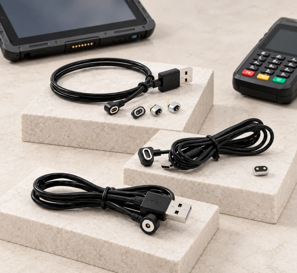
This combines a familiar USB power source with a magnetic interface that guides its mating parts into position.
The user brings the head toward the product rather than repeatedly inserting a USB plug. The magnets guide alignment, and the pogo contacts form the conductive charging connection.
It may suit products needing:
Frequent charging, compact housings, quick docking, blind mating, less repeated plug-in wear or a custom charging interface.
A magnetic cable connector can use a contact count suited to power alone or to additional signal requirements.
magnetic cable connectorA basic two-contact example carries:
Power + Ground
Four or five contacts can provide extra paths for signals, communication or device detection.
Magtor magnetic cable assemblies offer USB-A, USB-C, terminal-wire, bare-wire and custom connector ends. Contact count, length, wire gauge, magnetic force, cable direction and water-protection requirements can be configured for the device.
MagtorA 2 pin magnetic charging cable can link a USB-A or USB-C supply to a compact magnetic interface for basic charging.
2 pin magnetic charging cableChoose the USB end for the charging ecosystem, then choose the magnetic end for the device's electrical and mechanical requirements.
Matching the Interface to the Application
USB-C gives new electronic designs a compact reversible connector and access to newer implemented power and data technologies.
USB-A continues to serve existing chargers, computers, accessories and industrial equipment.
Select between them according to the application.
Prioritize USB-A where the product needs existing USB power sources.
Consider USB-C for newer devices where reversible connection, compact dimensions or modern USB charging support matters.
A compact device that does not need a USB receptacle on its housing may instead combine either source format with a custom magnetic pogo cable.
That retains a familiar source connection while letting the device-side interface follow its space, current, pin-layout and usability requirements.
Questions About USB-A and USB-C
Does a USB-C cable always transfer data faster?
No. The formats describe connectors. Data performance depends on the host, device and cable's supported USB specification, so a basic Type-C implementation can be slower than a higher-performance USB-A system.
Does every USB-C connection provide fast charging?
No. USB-C may implement USB Power Delivery, but the plug alone is insufficient. The charger, cable, power protocol and device must support the required charging level together.
Can a USB-A source charge a USB-C product?
Yes, with a correctly designed USB-A-to-USB-C cable for a compatible product. Many USB-C devices can use that arrangement, with performance limited by the source, cable and device.
Can a magnetic charging cable use either USB format?
Yes. A magnetic cable can have USB-A or USB-C at the supply end and magnetic pogo contacts at the product end.
How should an OEM choose the source connector?
USB-C often suits new products, and USB-A can suit an existing charger base. Also assess current, voltage, charging protocol, cable length, wire gauge and the structure of the device-side interface for the OEM project.