
Why Magnetic Connectors Heat Up: Finding and Reducing the Cause
Published on August 28, 2026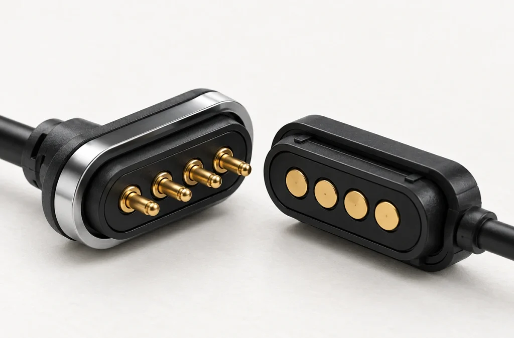
- Understanding Normal Temperature Rise
- The Role of Resistive Heating
- Conditions That Increase Connector Heat
- Locating the Source of Heat
- Reducing Heating in the Power Path
- Evaluating Temperature Rise in Testing
Current flowing through a magnetic connector's contact resistance dissipates power as I²R heat. Excessive current, misalignment, insufficient pin compression, contamination, worn plating, thin cables or undersized PCB traces can add to the temperature rise.
magnetic connectorIn most magnetic pogo interfaces, magnets align and retain the parts while the contacts carry current. The magnet is therefore usually not the primary heating point. Investigate the complete current path, rather than assessing the housing alone, to identify the cause.
Understanding Normal Temperature Rise
A conductive contact has some resistance, so carrying current normally causes a temperature rise.
temperature riseSlight warmth that stabilizes under continuous load does not necessarily mean a fault. The acceptable operating temperature depends on design, current, ambient temperature, enclosure, materials and the application.
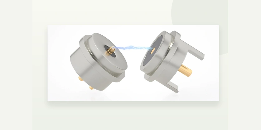
Investigate a rapid or continuing rise, a hot spot at one contact, or a marked temperature change after repeated use.
A cool-feeling outer housing can conceal a hotter pin, solder joint, cable termination or PCB transition. Locating such concentrated heat is therefore important.
The Role of Resistive Heating
Electrical resistance causes the power loss behind this heating.
The power dissipated as heat is described by:
P = I²R
The symbols denote:
P = power dissipated as heat; I = current; R = electrical resistance.
As current increases, this relationship makes resistive power loss more significant in the connector.
Consider an example with a contact-path resistance of 50 mΩ:
At 1 A:
P = 1² × 0.05 = 0.05 W
At 3 A:
P = 3² × 0.05 = 0.45 W
With resistance unchanged, tripling the current increases dissipated power by a factor of nine.
Performance observed at 1 A therefore does not establish how the same connector will behave under a continuous 3 A load.
Resistance itself can change. Wear, contamination, corrosion, insufficient compression and misalignment can increase it over the connector's use.
Conditions That Increase Connector Heat
Several conditions can cause overheating, so the stated current rating alone does not identify the source of a fault.
Continuous Load Above the Design Requirement
A contact system may tolerate a brief current peak but heat much more under a sustained load.
Specify peak current separately from continuous-current capability.
Longer operation gives the connector, cable, PCB and enclosure more time to accumulate heat.
For a high-current design, use the actual operating profile to select the interface, rather than the power supply's maximum output alone.
Elevated Contact Resistance
A magnetic charging connector can heat up when resistance at the mating contact becomes high.
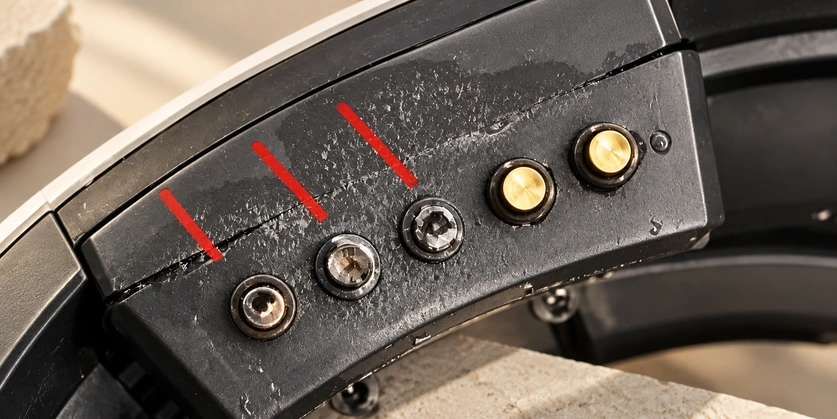
magnetic charging connectorContamination, oxidation, corrosion, worn plating, low contact force and mechanical damage can each raise resistance.
At a given current, higher resistance dissipates more electrical power at the interface.
In some conditions, degradation can reinforce the heating process:
Resistance increases → heat increases → contact-surface degradation accelerates → resistance increases further.
Assess resistance when the connector is new and again after repeated mating and environmental exposure.
Insufficient Spring-Contact Compression
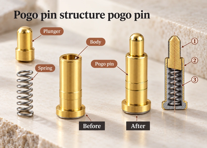
Stable pad contact requires the pogo pin to operate at a suitable working stroke.
Light compression can let a pin touch its pad without producing enough contact force.
The assembly may then look fully mated while its electrical connection remains unstable.
Too little compression may reduce effective contact area, raise resistance, interrupt charging and create local heating.
Excess compression can also stress the pin, PCB and housing.
Keep the pin within its specified working range.
Mating-Surface Misalignment
Magnetic attraction assists mating but does not by itself establish correct electrical alignment.
An offset between the two halves may move the pin onto a pad edge rather than its intended contact area.
Current may still flow, while the smaller effective contact area increases local resistance.
Combine magnetic guidance with mechanical features that control the mating position.
Housing shape, locating features, PCB position, magnet layout and pin working height all affect where the contacts meet.
Contamination, Sweat and Corrosion
Wearables, medical electronics, outdoor products and handheld equipment may expose magnetic contacts to contamination.
Dust, sweat, skin oils, moisture, salt and other residues may collect on the contact surfaces.
Even a thin residue layer can affect the electrical behavior of a compact contact.
Intermittent charging may be the first sign. If resistance increases, the same contamination can also contribute to a higher temperature.
For humid, dusty or sweat-exposed use, assess corrosion resistance together with water protection.
Resistance in Cables and PCBs
The hottest point may be outside the magnetic connector itself.
A typical charging power path includes:
Power supply → cable → termination → connector → mating contact → PCB → load.
Each stage adds resistance to that path.
Thin wire, a narrow PCB trace, a poor solder joint, a weak crimp or limited copper area can add voltage drop and heat.
A higher-current connector will not necessarily solve the problem if the cable or PCB still lacks the required capacity.
Locating the Source of Heat
Investigate the complete current path when tracing a thermal fault.
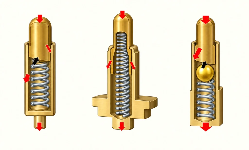
Measure the current during actual operation and record the continuous level, peaks and duty cycle. The charger or power supply label alone does not describe that profile.
Then measure the connector's voltage drop with the load applied.
At unchanged current, an increased voltage drop suggests higher resistance somewhere across that interface.
Compare contact resistance over these stages:
New connector → after mating cycles → after environmental exposure.
The comparison can help identify changes associated with wear or contamination.
Measure temperature at several points along the path.
Check the pin interface, mating pad, housing, cable termination, solder joint and PCB transition.
Thermocouples provide readings at individual points; a thermal camera can help locate concentrated hot areas.
thermal cameraOne initial question is:
“What temperature does the connector reach?”
Follow it with:
“At which point does the temperature rise start?”
Comparing locations can distinguish a contact-interface fault from a cable, PCB or other charging-system problem.
Reducing Heating in the Power Path
Reduce resistance and ensure every part of the path is designed to carry the required operating current.
A higher-current application may need larger power contacts rather than identical small pins for every electrical function.
Parallel power contacts are another possible approach, with careful attention to current sharing. Two parallel contacts do not automatically double capacity because the current may divide unequally.
Control the working stroke and contact force consistently.
Set a repeatable mating position using the housing or a mechanical stop. Do not rely on the pins to stop the product's travel.
Select contact surfaces for the intended environment and mating life.
Wearable and outdoor use makes plating, corrosion protection, cleaning strategy and moisture control important design considerations.
Evaluate the connector, cable and PCB as one assembly.
Increasing pin capacity has limited value if wire gauge, trace width, solder joints or terminals remain the weakest part of the path.
Also assess the thermal environment surrounding the interface.
An open-air test may give a different operating temperature from installation in a small sealed enclosure near a battery, processor or other heat source.
Evaluating Temperature Rise in Testing
A meaningful test needs to approximate the product's actual operating conditions.
Apply the intended continuous current and monitor voltage drop, contact resistance and temperature.
Keep the load applied until temperature approaches a stable condition. A cool reading in the first minute does not show whether the assembly will continue warming during longer use.
Repeat the assessment after mechanical aging.
Repeated docking can affect plating, contact surfaces, spring behavior and resistance. Compare temperature performance before and after mating-cycle testing to assess these changes over use.
Moisture, sweat, salt, dust or elevated ambient temperature may also require an appropriate environmental test program.
For a higher-current design, include the full assembly in temperature-rise testing:
Connector + cable + termination + PCB + enclosure.
Testing the pin alone does not cover this complete path.
The assembly-level result gives a better basis for evaluating the finished device's available thermal margin.
Assessing Heat Across the Complete System
Electrical resistance dissipates power as heat when current flows through a magnetic connector. Higher current or resistance can increase the potential temperature rise.
Possible causes include excessive current, high contact resistance, insufficient compression, misalignment, contamination, worn plating, cable resistance, PCB limitations and inadequate heat dissipation.
Diagnose the entire power path when a magnetic connection overheats.
For a custom design, assess current capacity with working stroke, contact force, pin allocation, plating, wire gauge, PCB design, enclosure temperature and expected mating life.
Magtor magnetic connector and pogo pin solutions can be tailored for higher charging-current requirements or repeated docking. Design inputs include available space, required current, magnetic force, working height, plating, cable assembly and the operating environment.
Magtor