
How a Charging Dock Works: Power, Contacts and Alignment
Published on August 28, 2026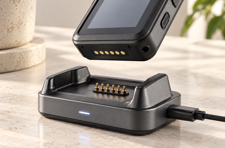
- What a Charging Dock Does
- The Dock's Charging Sequence
- Charging Interface Options
- Why Docks Use Spring Contacts
- Designing a Reliable Dock
- Selecting the Dock's Connector
A dock first locates the device, then supplies power through its chosen interface: USB-C, wireless charging, fixed contacts, pogo pins or a magnetic connector. Alignment, contact resistance, working stroke, current capacity and connector design all affect reliable docking.
The interface matters especially when users repeatedly dock and remove a product. It needs to align the parts, maintain electrical contact and carry the required current, while making routine charging convenient without connecting a cable each time.
What a Charging Dock Does
A charging dock is a base, cradle or station that supports a device while providing power to recharge its battery.
Typical products using docks include handheld terminals, barcode scanners, tablets, medical devices, radios, wearables, smart-home equipment and other rechargeable electronics.

In addition to supplying power like a wall charger, a dock usually positions the product and establishes its charging connection at the same time.
A dock may supply power alone or add data transfer, identification, communication or accessory functions.
The application determines the layout. A smartwatch may use a small magnetic cradle, whereas an industrial handheld can use a larger dock with spring-loaded contacts.
Both arrangements aim to make charging easier by letting the user place the device in its seat rather than insert a connector on every occasion.
The Dock's Charging Sequence
A typical conductive charging path passes through these stages:
Power source → dock electronics → charging contacts → device charging circuit → battery.

The dock takes power from an external input, which may be a USB-C adapter, an AC supply or another DC source.
USB-CIts interface then carries the voltage and current required by the device.
Cradle geometry, mechanical guides or magnets position the product as it enters the dock. In a contact-based interface, power can reach the device once the conductive surfaces engage.
The charging circuit inside the product controls the battery's charging process.
Separate these roles in the design: contacts generally establish the conductive path, while battery-management electronics control charging.
More complex docks may allocate extra contacts to the following functions:
device detection
identification
data communication
status signals
charging control
A basic dock may need only positive and negative power contacts. An industrial product may require several additional signal paths.
Charging Interface Options
Docks do not all use the same connection method. Select an interface against device size, charging power, docking frequency, environment and mechanical design.
| Charging Method | Main Advantage | Typical Limitation |
|---|---|---|
| USB-C | Standardized power and data | Requires physical plug insertion |
| Fixed metal contacts | Simple structure | Limited tolerance compensation |
| Pogo pins | Spring-loaded, repeatable contact | Requires controlled compression |
| Magnetic pogo pins | Automatic alignment and electrical contact | Magnetic and spring forces must be balanced |
| Wireless charging | No exposed electrical contacts required | Can add heat, cost, and alignment requirements |
Scroll horizontally to view every column.
USB-C
USB-C can carry power and data through a compact reversible connector. USB-IF describes the Type-C system as supporting smaller, thinner devices with scalable power and performance; the implemented system determines its actual functions.
A desktop dock may use USB-C at the external power input or at the connection to the device itself.
The plug still has to enter a receptacle, which can be less convenient for a device docked dozens of times during a day.
Wireless Charging
Wireless charging transfers power by electromagnetic coupling, without requiring exposed conductive charging contacts.
Wireless charging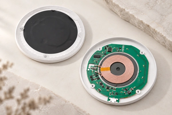
The Wireless Power Consortium develops Qi, a widely used wireless-power standard.
A sealed surface or a design without an external connector may favor wireless charging. Coil alignment and thermal management still need attention, particularly at higher charging power.
Pogo Pin Charging Contacts
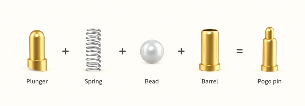
Pogo pins make electrical contact using a spring-loaded plunger.
Docking pushes the device's contact surface against the pin, compressing it slightly. The internal spring keeps pressure on the mating pad.
Handheld products such as barcode scanners and mobile two-way radios commonly use pogo contacts in their charging docks.
These contacts can therefore suit a device that is repeatedly placed into and removed from a dock.
Why Docks Use Spring Contacts
A device will not necessarily arrive at exactly the same position on every docking cycle.
Housing dimensions, PCB location, molded parts, assembly tolerances and user placement can each introduce small positional differences.
A rigid contact has little travel available to accommodate those differences.
The spring travel of a pogo pin provides that adjustment.
At the final docking position, a pogo pin remains compressed against the mating pad. Its spring travel can accommodate a limited amount of positional variation while maintaining contact pressure.
That ability is useful in interfaces designed for repeated mating and separation.
Combining Pogo Pins with Magnetic Alignment
Magnets can be added to an interface using pogo contacts.
In a magnetic pogo interface, the components divide their tasks:
Magnets → positioning and retention.
Pogo pins → conductive connection.
Attraction guides the device toward its seat. Once seated, the pins engage the conductive pads and carry power.
Compact products can use this arrangement to provide a simple place-and-charge docking experience.
A magnetic charging connector can avoid manual plug insertion while keeping a direct conductive power path.
Potential uses include wearables, medical electronics, handheld products, sensors, charging cradles and other compact rechargeable devices.
Designing a Reliable Dock
The correct pin count is only one requirement for a reliable charging dock.
Design the mechanical positioning and electrical contact system together.
Working Stroke
Each pogo pin is designed for a particular travel range.
Docked pins need to stay within their intended working stroke. Insufficient compression can leave unstable contact, and excessive compression can increase mechanical stress.
Use the dock structure to set the product's final position; the pins should not serve as mechanical stops.
Contact Force
Spring pressure supports the electrical connection.
Low force may allow vibration, dimensional variation or contamination to interrupt charging.
Unnecessarily high force, especially across several pins, can make docking harder and load the housing or PCB.
For a multi-contact interface, assess the combined force of all pins as well as the force per pin.
Contact Resistance
Resistance is present in every conductive connection.
Higher resistance produces greater voltage drop and can increase heat at the contact area.
In a dock, the following can affect contact resistance:
Surface contamination, plating condition, contact force, working stroke, wear, corrosion and the mating surface.
Give these factors particular attention as charging current increases.
Required Charging Current
A small wearable and an industrial handheld can have substantially different charging-current needs.
Define the charging current early: it influences pin size, the number of power contacts, cable size, PCB routing, contact resistance and thermal performance.
A higher charger output does not establish that the existing contact system can carry the added current safely.
Plating and Operating Environment
A dock's exposed interface may encounter dust, skin oils, moisture, sweat or industrial contamination.
Gold plating is commonly used on connector contacts to support conductivity and resist surface degradation during repeated use.
Plating alone does not determine the performance of the complete contact system.
Review the expected environment, mating cycles, contact force, current and cleaning requirements together.
Controlling Mechanical Alignment
Compact docks need carefully controlled contact alignment.
A device can appear seated even when offset pads leave one or more pins only partly engaged.
Guide walls, locating features, magnets and mechanical stops may be used separately or together to set the final position.
Retention is only part of the objective. The electrical contacts also need to reach a repeatable working position on each docking cycle.
Selecting the Dock's Connector
Choose the interface according to the device's actual pattern of use.
USB-C may be sufficient for a product that is disconnected only occasionally.
Wireless charging may suit a sealed product where exposed charging contacts are undesirable.
Pogo pins or magnetic pogo pins may suit frequent docking, fast automatic positioning or a product with limited internal space.
The electrical system also determines how many contacts are needed.
A 2 pin charging connector may be enough for positive and negative power paths alone.
2 pin charging connectorA 3 pin connector adds a path that may serve detection, identification or another project-specific function.
3 pin connector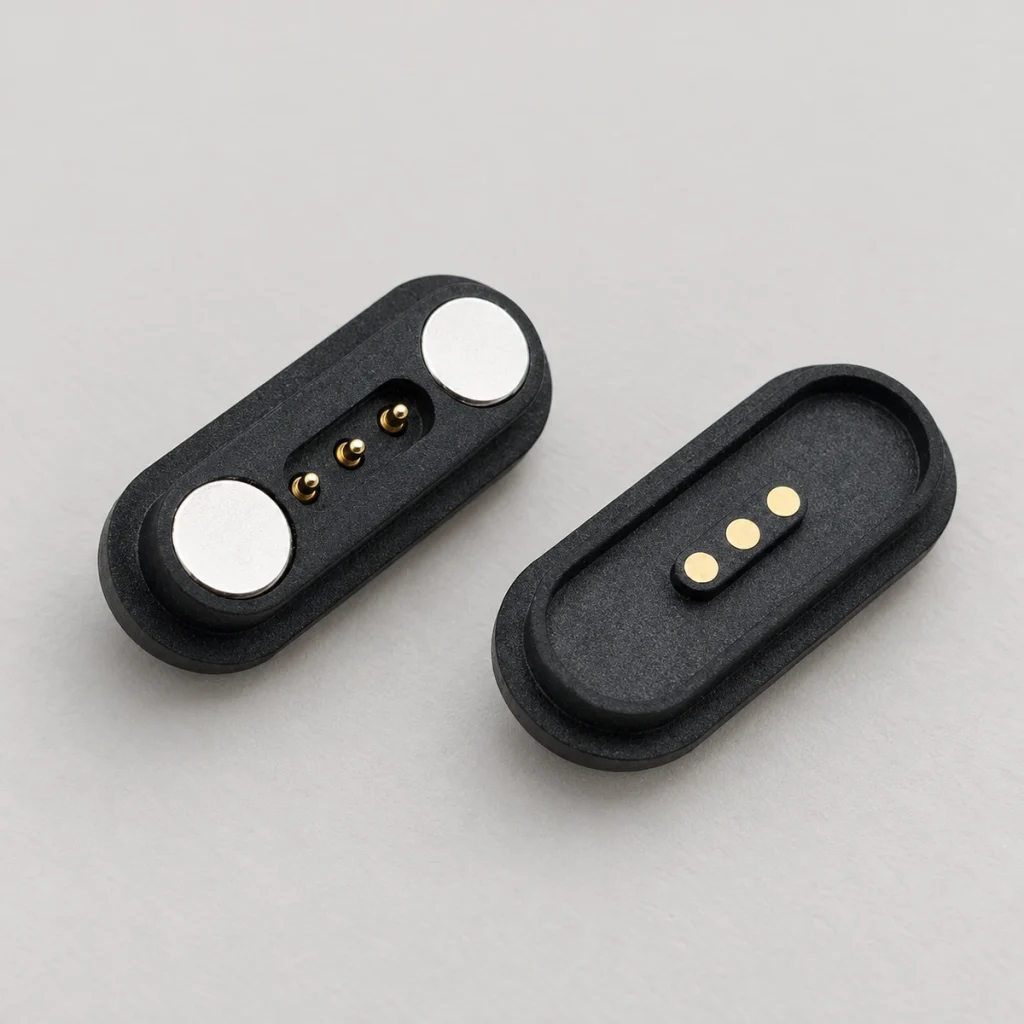
Four, five, six or more contacts can accommodate power alongside signals, ID detection, communication or multiple electrical paths.
For a custom product, select a connector that fits the housing and PCB design requirements rather than reshaping the product around an unsuitable standard interface.
Define the following inputs early in development:
Available connector space; charging voltage and current; PCB position; working height; pin pitch; magnetic force; mating cycles; waterproof requirements; contact plating; cable direction; and signal requirements.
waterproof requirementsWhere automatic magnetic docking is required, a custom magnetic pogo pin connector can integrate spring contacts and magnetic alignment into a compact interface.
Magtor supplies custom magnetic connector and pogo pin connector solutions for docks and compact electronics. Available configurations include 2 pin, 3 pin, 4 pin, 5 pin, 6 pin and other custom layouts.
Magtormagnetic connector and pogo pin connectorBringing the Dock Design Together
A charging dock positions the product and delivers power to its charging circuit. The product may use USB-C, wireless charging, fixed contacts, pogo pins or magnetic pogo pins for that connection.
For frequent docking, spring contacts accommodate small mechanical variations while maintaining contact pressure. Magnetic guidance can further simplify the user's placement of the device.
Assess positioning alongside the electrical requirements. Current, contact resistance, working stroke, spring force, plating, magnetic force, contamination and housing tolerances all affect charging performance over the intended service life.
Addressing the charging interface early in a compact device's mechanical and PCB design can reduce later docking and reliability problems.