
How an Earbud Charging Case Delivers Power to the Earbuds
Published on August 27, 2026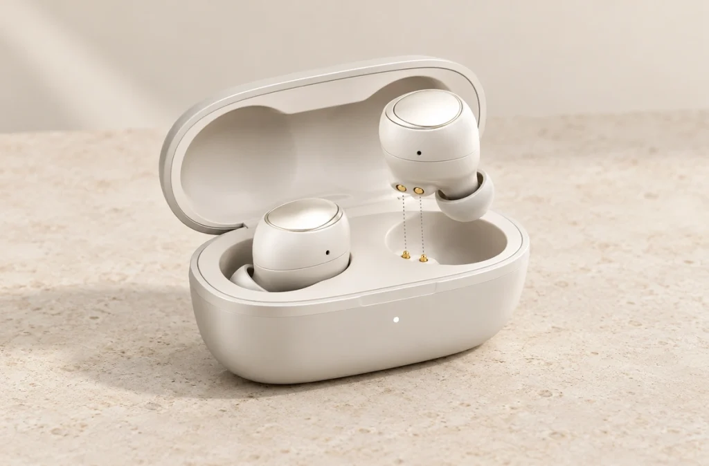
- The Charging Case's Power Path
- Identifying the Spring Contacts
- Why Earbud Cases Use Pogo Pins
- Causes of Charging Failure in the Case
- Designing Reliable Earbud Charging Contacts
- Applying the Principle to Magnetic Connectors
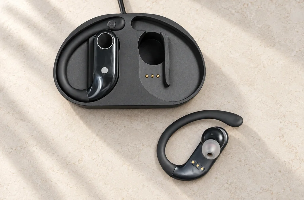
Many wireless earbuds receive charging power through physical contacts in their case. Spring-loaded pogo pins press on the earbuds' metal pads, while magnets and the cavity geometry help align the parts. The case battery supplies the power needed for repeated charging.
The Charging Case's Power Path
An earbud case protects the earbuds during storage and carries a portable energy supply for recharging them.
Most cases contain a rechargeable battery and power-management electronics. An input such as USB-C, wireless charging or another power connection replenishes that battery, storing energy for later earbud charging.
USB-Cwireless chargingReturning an earbud to the case can establish the following power path:
Case battery → power-management circuit → charging contacts → earbud charging circuit → earbud battery.
The case must do more than hold a battery. It manages power delivery, detects charging conditions, protects the battery system and maintains an electrical connection to each removable earbud.
Battery charging is controlled by the electronics, rather than by the contact pins. The contacts provide the conductive path between the removable earbud and the circuitry in the case.
Identifying the Spring Contacts
The small metal pins that move inside many charging cavities are spring-loaded contacts, commonly called pogo pins.
Each pogo pin has a moving plunger and an internal spring. Seating the earbud pushes its contact pad against the plunger, compressing it slightly; the spring maintains pressure on the pad.
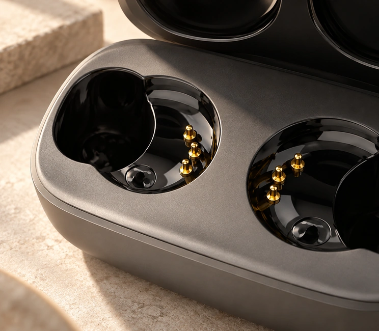
DigiKey describes pogo pins, or spring-loaded contacts, as electrical contacts for repeated mating and for accommodating variation in mechanical position. Charging cradles are one example of their use.
The pin's working stroke accommodates small dimensional differences when an earbud enters the case, so the earbud does not need to stop at an exactly identical position every time.
A design may use two contacts for positive and negative charging connections. More contacts can be included for detection, identification, testing or other project-specific signals.
The complete electronic design determines the signals carried by those contacts; their number alone does not define the interface's functions.
Why Earbud Cases Use Pogo Pins
Earbud charging combines demanding space and connection requirements.
The contacts must fit a very small interface and handle earbuds being removed and docked several times a day. Users also expect charging to start after docking, without having to insert a cable into each earbud.
Spring-loaded contacts can support repeated docking while keeping the charging interface compact.
Housing, case, PCB and contact positions all have manufacturing tolerances. Unlike a fixed contact that needs closely controlled positioning, a pogo pin provides controlled vertical travel to accommodate those variations.
Many cases add magnetic positioning to their spring contacts.
The magnet's role is generally to guide the earbud into position and hold it in the cavity; the magnet need not be part of the conductive charging path.
The docking and charging sequence can be described as follows:
Earbud approaches the case → magnetic or mechanical guidance aligns it → pogo pins compress onto contact pads → conductive connection forms → charging starts.
This arrangement can help compact wearables where a conventional USB connector would need too much space or require the user to insert a plug.
Causes of Charging Failure in the Case
A charging fault does not necessarily mean the earbud battery has failed.
The small mating surfaces need to make contact correctly. Dirt on those surfaces or an earbud seated incorrectly can interrupt charging.
The device manufacturer’s guidance recommends keeping the charging contacts on both the case and earbuds free of dust, wax and debris. It also identifies incorrectly fitted ear tips or wingtips as a reason an earbud may not sit correctly in its charging cavity.
charging contacts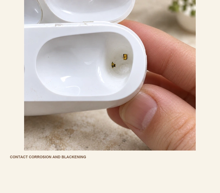
Similar charging symptoms can result from several mechanical or electrical conditions:
Contact surfaces covered by dirt, earwax or dust
Sweat or moisture near the charging contacts
An earbud not fully seated in the cavity
A pogo pin unable to move freely
Too little spring compression
Contact plating that is worn or damaged
Higher contact resistance
Damaged case or earbud electronics
Cleaning can restore a contact path disrupted by contamination even when the battery remains healthy, which explains why it can resolve some charging faults.
For the product designer, cleaning is only part of the problem. The interface also needs to accommodate normal dimensional variation, repeated docking and the earbuds' expected operating environment.
Designing Reliable Earbud Charging Contacts
Choosing a small pogo pin is only one step in specifying an earbud charging interface.
Assess the interface as a complete mechanical and electrical system.
Working Stroke and Contact Force
The pin needs enough compression to maintain contact. Excess travel can instead stress the pin, PCB or housing, so the working position must stay within the design requirements.
Define a final seating position in the case to control that compression.
Magnets can draw the earbud into place, but should work with the cavity, housing surfaces and mechanical stops to control its final position. These features also determine how far the pins compress.
Contact Resistance
A conductive charging contact introduces electrical resistance into the path.
Higher resistance can increase voltage drop and heat generation. A stable contact path matters particularly for compact earbuds using low-voltage batteries.
Factors that can change contact resistance include:
Contamination at the surface, contact force, plating condition, wear, corrosion and working stroke.
Evaluate these effects across the entire charging path, rather than relying on the specification of one pin alone.
Contact Surface Plating
Handling, moisture and contamination repeatedly affect exposed charging surfaces.
Gold plating is often selected for its conductivity and corrosion resistance. Its thickness on its own, however, does not establish a long service life for the complete interface.
Durability also depends on the contact material, spring force, mating movement, target surface, contamination and electrical load.
Moisture and Sweat Exposure
During everyday use, earbuds encounter sweat, skin oils, earwax and humidity.
A housing's water-resistance rating does not establish permission to energize its exposed charging contacts while they are wet.
water-resistance ratingReview drainage, contact location and corrosion-resistant surface treatments, together with whether the charging circuit should stay powered when the contacts are exposed.
Coordinating Magnetic Alignment
Magnetic guidance can reduce the effort needed to dock an earbud for charging.
Attraction can guide the earbud toward its seat, reducing the need for precise placement by hand.
Match magnetic force to pin spring force, case geometry and the force needed to remove the earbud. Weak attraction may leave an unstable contact; excessive attraction can make removal uncomfortable or impose unnecessary impact on internal parts.
Applying the Principle to Magnetic Connectors
The contact and alignment principle in an earbud case can also be used in other compact electronic products.
A custom charging interface can bring together these elements:
Spring-loaded pogo pins + conductive contact pads + magnetic alignment + a custom housing.
Together, they can form an interface that mates as its two parts approach each other.
Products that may use this approach include:
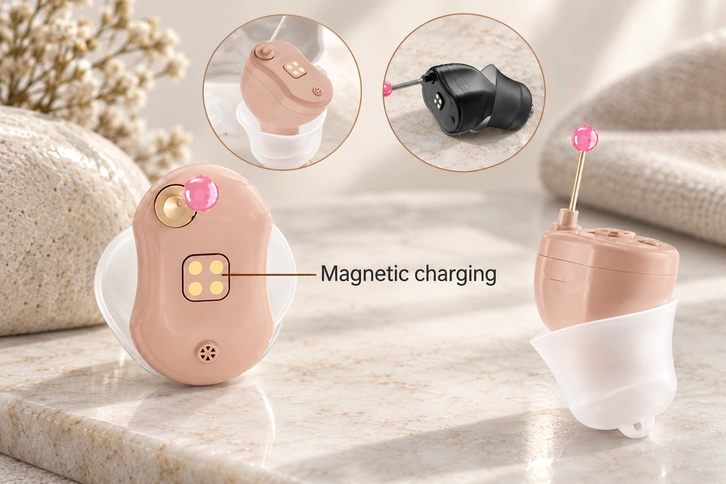
Examples include smart wearables, hearing devices, smart rings, medical electronics, handheld equipment, sensors and other compact rechargeable devices.
For basic charging, a 2 pin magnetic connector may carry power and ground.
2 pin magnetic connectorA 3 pin magnetic connector or a design with more contacts may be suitable when detection or another electrical function is required.
3 pin magnetic connector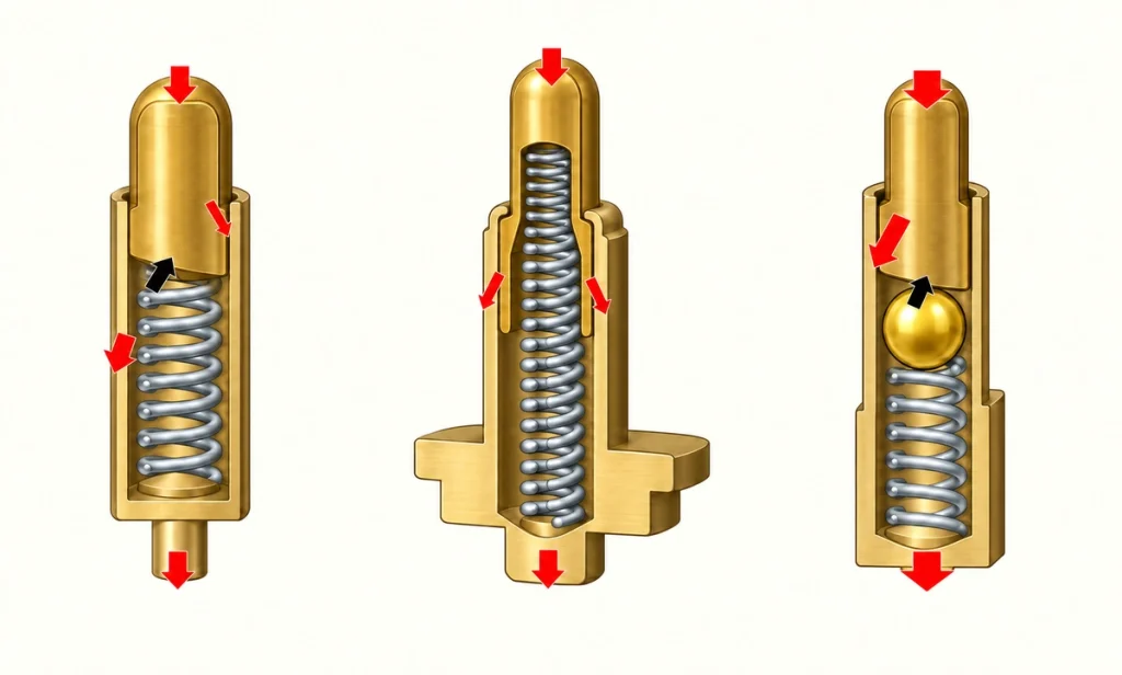
Additional contacts can be assigned to power, ground, identification, signals or communication specific to the project.
Let the device's requirements guide the connector design so its contact interface suits the product.
In a custom project, charging performance depends on connector dimensions, pin pitch, working height, spring force, magnetic force, plating, PCB position, required current and housing geometry.
A custom magnetic pogo pin connector can address that combination of constraints.
Magtor develops pogo pin and magnetic connector solutions for compact charging and docking. Two-pin, three-pin and multi-contact designs can be adapted to different device layouts and electrical requirements.
Magtormagnetic connectorAt the start of an earbud, wearable or charging-case project, supply the device dimensions, PCB layout, required current, available connector space and intended docking method. These five inputs help identify a suitable standard interface or define a custom one.
Understanding the Complete Charging Interface
In many cases, wireless earbuds charge through a conductive connection to their case. Spring-loaded pins in the case press on metal pads on the earbuds, while magnets and mechanical features hold the parts in alignment.
The visible contacts are only part of the system. Long-term charging performance also depends on working stroke, spring force, contact resistance, plating, contamination, magnetic alignment and the case geometry.
The case illustrates why pogo pins and magnetic connectors are useful in compact rechargeable electronics: a small, repeatable docking interface can connect power without a conventional plug and simplify everyday use.
Wireless Earbud Charging: Frequently Asked Questions
Is the connection from the case to an earbud always wireless?
No. A case may receive power through wireless charging, while the earbuds inside it use metal contacts. Many designs send charging current from the case through pins or pads directly to each earbud.
What are the small gold-colored pins in the case?
They are commonly spring-loaded electrical contacts called pogo pins. Inserting the earbud compresses them slightly so they maintain contact with its metal pads.
What role do magnets play during earbud charging?
Magnets can guide the earbud into its seat and retain it there during charging. Conductive contacts usually carry the electrical current; the magnets primarily provide positioning.
Can contamination interrupt charging in the case?
Yes. Dust, earwax, moisture and other contamination can disrupt the connection between the case and the earbud. Cleaning the contact area is therefore a common troubleshooting step.
Can an OEM customize the earbud's pogo contacts?
Yes. OEM selection or customization can cover pin diameter, height, working stroke, spring force, plating, current rating, PCB mounting and magnetic alignment, according to the space and charging requirements of both the earbud and case.