
How Magnetic Charging Connectors Work: From Alignment to Conductive Paths
Published on August 26, 2026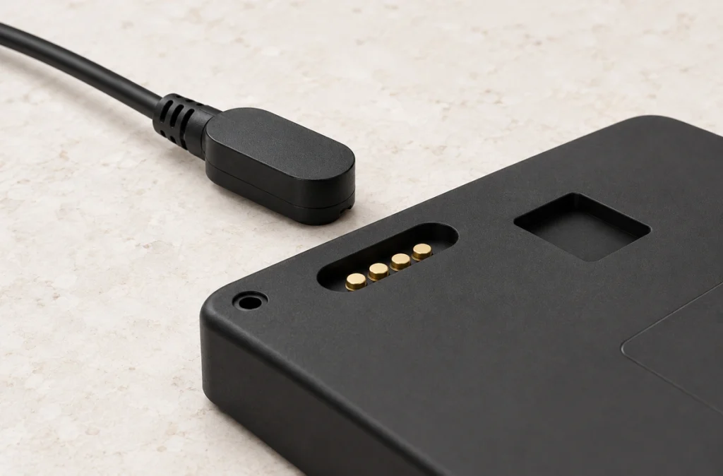
- The conductive charging sequence
- Magnetic guidance and retention
- Spring contacts and working travel
- The supply and return paths
- Allocating contacts for supply and signals
- Contact charging and inductive charging
- Requirements for a stable mating interface
In a magnetic contact charger, magnets guide and retain the mating pair while spring-loaded or other conductive contacts carry the assigned electrical paths. After engagement, the device’s charging electronics manage energy delivered to the battery. Verify the complete interface for its load and docking duty.
Magnetic contact-charging interfacesVideo material pending replacement
Three-Contact Magnetic Connector: Illustrated Structure and Mating Action
Conductive magnetic charging requires physical metal contact. Qi and magnetic Qi2 charging transfer energy through coupled coils instead. Both may use magnets for positioning, but their energy-transfer paths differ.
Qi or magnetic Qi2 chargingThe conductive charging sequence
The interface can be described by this simplified path:
Source supply → Cable → Magnetic mating head → Spring contacts → Device pads → Charging electronics → Battery
Magnetic mating headVideo material pending replacement
As the mating halves enter the designed capture range, magnets assist positioning. The spring contacts compress against the corresponding conductive pads as the housing reaches its intended mating position.
With the required engagement and contact pressure established, the assigned electrical paths connect and power can enter the device.
The connector does not normally implement battery-charging control. The device electronics manage current, voltage, battery condition and charge termination according to the charging system.
Treat the connector as the electrical and mechanical interface between the supply arrangement and device.
Magnetic guidance and retention
Magnetic guidance assists the initial mating action.
A typical construction places permanent magnets beside or around the contacts. They attract the matching half at close range, in combination with its housing and polarity arrangement.
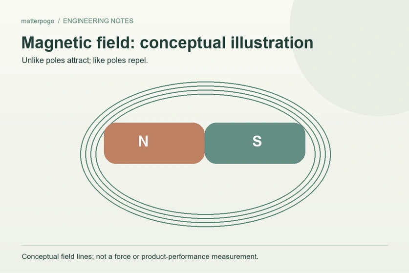
The magnetic arrangement assists positioning and supplies retention for the intended contact engagement. Specify both functions with the installed spring reaction and external loads.
This can reduce manual positioning compared with a plug-in interface, within the designed capture range.
Select retention for the application rather than maximizing it.
Insufficient retention may allow cable movement to separate the interface. Excessive retention can make removal difficult or transmit more handling force to the device.
Review retention with mating-head size, device weight, cable routing, spring reaction and the intended release action.
A suitable mechanical arrangement may prevent reversed engagement or incorrect polarity. Confirm those features for the specific design.
Spring contacts and working travel
Once the mating halves are positioned, the contacts establish the conductive interface.
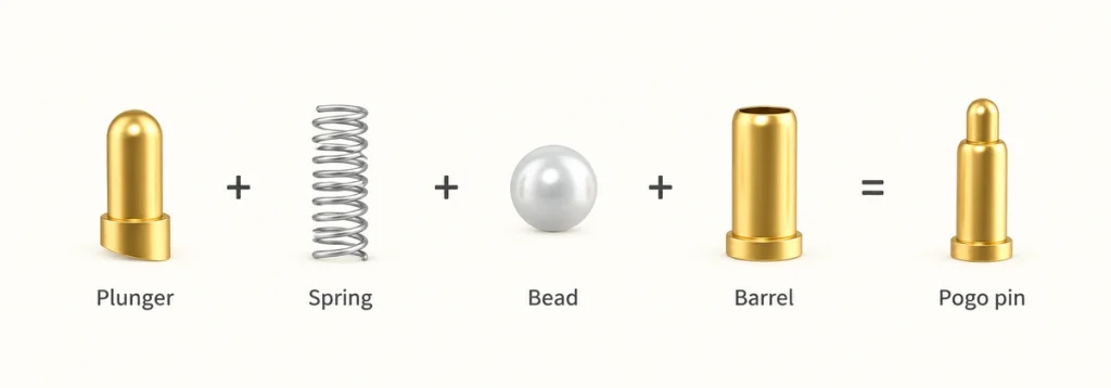
A typical spring contact uses a plunger, barrel and internal spring. Mating compresses the plunger against a corresponding conductive pad within its specified working range.
Spring compression applies contact force and can accommodate limited height variation or movement. Validate the geometry and operating duty; this mechanism alone is not a vibration or misalignment rating.
Manufacturer spring-contact descriptions distinguish free and working heights and the matching contact surface. Use the selected part’s specified geometry and travel rather than assuming a general tolerance for lateral misalignment.
Magnets guide and retain the joint; spring travel accommodates limited axial separation between its contact surfaces. The two mechanisms have different roles.
Too little compression can leave inadequate contact pressure. Exceeding the intended travel can stress the spring or interface, so check installed height against the specified range.
Review working height, spring force, pad location and magnetic retention together to establish the required mating condition.
The supply and return paths
Engaged pins and pads create conductive paths with finite contact resistance.
A simple two-contact example may allocate one supply contact and one return.
A simplified supply-and-return illustration is:
USB supply or adapter → Cable → V+ contact → Device charging electronics and battery circuit → GND return contact → Source
The internal charging circuit controls delivery to the battery. The illustration is not a complete battery-charging schematic.
Magnets provide positioning and retention; they do not supply the charging energy. Conductive metal contacts complete the electrical paths.
Include contact resistance in the electrical review.
Contamination, insufficient force, worn surfaces, corrosion or an unsuitable finish can increase resistance. At the actual load, this may increase voltage drop and contact heating.
Evaluate current, voltage, contact resistance, spring force, finish, conductor size and operating temperature as one assembly rather than using retention as the main electrical criterion.
Allocating contacts for supply and signals
A magnetic contact interface can contain more than two positions.
Two positions may suit supply and return. Additional positions can carry defined data, identification, detection or control paths where the electronics and cable implement those functions.
Possible contact functions are:
| Assigned function | Illustrative use |
|---|---|
| V+ | Supply input |
| GND | Supply return |
| Data+ / Data− | Implemented data paths |
| ID | Device or accessory identification |
| Detect | Mating detection |
| Control | Charging or system-control path |
Scroll horizontally to view every column.
There is no universal pin map for most dedicated magnetic spring-contact interfaces. Define every assignment from the device circuit and application requirements.
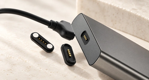
A Magtor six-contact configuration can be reviewed for a combination of supply, returns, data, identification, detection or charging-control functions. Confirm the chosen map; six positions do not automatically provide every listed function.
six-contact magnetic interfaceSome layouts use parallel contacts for supply or return. Verify sharing, voltage drop and temperature rise before assigning a total load; do not simply multiply one contact’s rating.
Choose the count from the required electrical paths and available space rather than selecting the largest arrangement.
Contact charging and inductive charging
The use of magnets in both approaches can obscure their different electrical mechanisms.
In contact charging, magnets assist mating and conductive pins or pads physically touch. Current crosses that metal interface.
In a magnetic Qi2-type system, magnets assist transmitter-to-receiver positioning. Energy crosses the interface through induction between the two coils, rather than through exposed mating contacts.
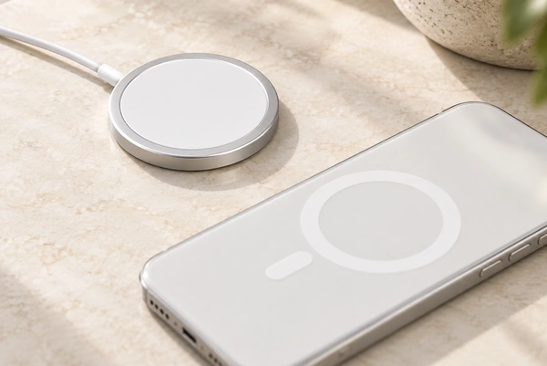
The Wireless Power Consortium describes an alternating current in the transmitter coil creating a field that induces voltage at the receiver. Alignment magnets support coil positioning; they are not conductive charging paths.
These mechanisms lead to different product-design requirements.
A contact interface can combine supply and assigned signals within a small mating area. Wearables, compact medical equipment, handheld devices, connected products, docks and specialized industrial equipment are possible uses, subject to their own safety and exposure validation.
Inductive charging avoids exposed conductive charging contacts, but needs transmitter and receiver coils, suitable spacing, thermal management, controls and internal area for the system.
Compare product dimensions, load, exposure, cost, charging speed, signals and user interaction. Neither mechanism is the better choice for every device.
Requirements for a stable mating interface
Placing magnets beside spring contacts is only the starting point for a complete interface design.
Provide the required contact pressure and retention throughout the specified working travel. The housing must align each contact with its intended pad under the relevant tolerances and loads.
Materials and finish also affect performance through the intended service duty.
Commercial spring contacts may use gold-plated surfaces and have defined repeated-mating ratings. Those ratings vary with the selected geometry and test conditions and do not transfer to a different assembly.
Assess sweat, dust, moisture, oils and metal contamination at exposed contacts. Outdoor, medical and industrial equipment may need additional sealing or corrosion measures, with cleaning and safety requirements verified separately.
Before finalizing an OEM interface, establish thirteen inputs: current, voltage, pin assignment, contact resistance, working travel, spring force, retention, mating-life target, routing, conductor size, finish, ingress requirement and available space.
Magtor can review contact count, USB-A, USB-C or bare-conductor ends, exit direction, retention, length, conductor size and sealing requirements against the device design. Confirm the selected options and electrical functions; USB-C shape alone does not establish PD or high-speed data support.
MagtorUSB-CFrom mating action to a complete design
Magnetic guidance and conductive transfer are separate functions: magnets position and retain the pair, while the metal interface carries the assigned electrical paths.
Within the capture range, mating brings the pins onto their pads and compresses them into the specified working position. The completed paths deliver supply to the device’s charging electronics, which manage the battery circuit.
Two positions may provide supply and return for a simple product. A multi-contact layout can add implemented data, identification, detection or control paths when both halves and the cable support them.
Balance retention, spring force, working height, resistance, contact mapping, load, finish and housing geometry, then validate the representative assembly.
A dedicated magnetic spring-contact interface may suit a compact product with repeated docking and guided attachment requirements. Its usefulness follows from matching the complete interface to the device, rather than from magnets alone.