
How to Choose a Magnetic Cable Connector That Fits Your Device
Published on August 25, 2026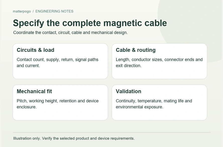
- Define the device requirements
- Allocate the contact count
- Specify the electrical load and signals
- Choose cable length, conductors and the opposite end
- Review retention and the mechanical layout
- Set exposure, life and customization requirements
Choose a magnetic cable as a complete device interface: establish the contact functions, current, voltage and signals, then match cable length, conductors, retention, available space and operating conditions. Validate those choices together for the required charging, communication and docking duty.
magnetic cable interfaceDefine the device requirements
Begin with the tasks the interface must perform in the actual device.
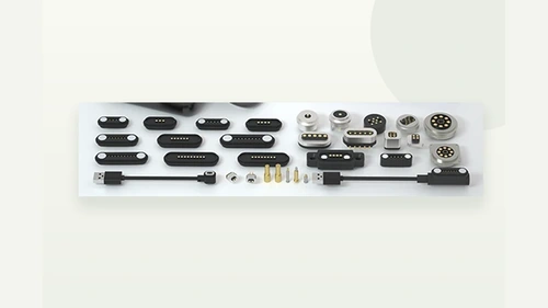
A wearable that only charges a battery may need a compact two-contact head. An industrial terminal carrying power, signals and engagement detection can need additional contacts, different conductors and a more substantial mechanical arrangement. Develop each interface from its own duty.
Establish voltage and load first, then list any data, identification, sensing or control functions alongside charging. Check the available PCB area and enclosure clearance at the same time so electrical choices fit the product.
Exposure changes the requirements. A desktop product may have different sealing and corrosion needs from a wearable, outdoor sensor or medical device subject to sweat, moisture or repeated cleaning. Specify the actual exposure rather than transferring another product’s protection rating.
Select the interface to suit the device requirements and evaluate any changes needed to use an existing configuration.
Allocate the contact count
Count the separate electrical paths before deciding how many contact positions are needed.
Two positions may provide supply and return for simple charging. A third can support a defined identification or signal function; four or five offer further options for charging with communication. Eight positions allow more allocation choices for supply, returns and several signals, where the complete design supports them.
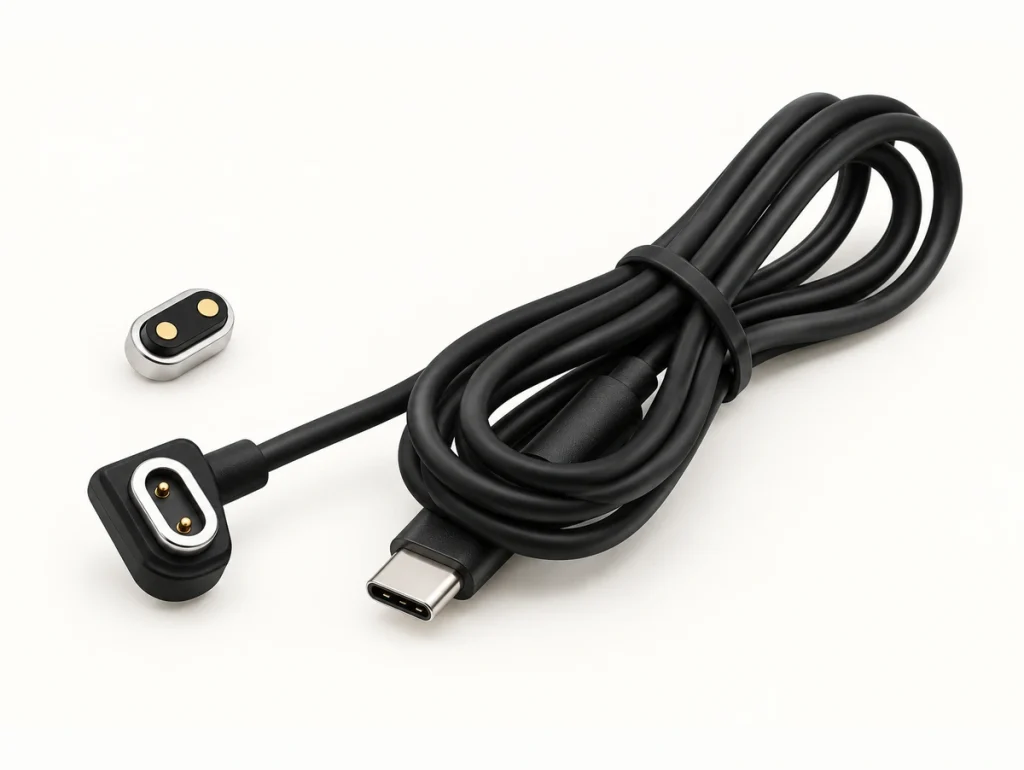
A contact count does not establish a standard pinout.
One four-contact layout could assign supply, return and two signals. Another could use two contacts for supply and two for return in parallel. The latter requires verified current sharing and thermal performance; the count alone does not establish a higher rating.
four-contact magnetic interfaceAssign every function before finalizing the mating geometry. An OEM layout can then follow the PCB routing, current paths and specified communication interface.
PCBSpecify the electrical load and signals
Check that the chosen construction supports the load after establishing the contact functions.

Current capacity depends on contact dimensions, material, finish, resistance, cable conductor size and the power-path allocation. Evaluate these features in the installed assembly rather than calculating a rating from the number of pins.
A low-power wearable may suit smaller contacts. A several-amp load can call for larger contacts, larger conductors or appropriately validated parallel paths, depending on voltage drop, temperature rise and the operating duty.
Keep voltage within the verified insulation and spacing limits. Closely spaced contacts in a small interface need particular attention to this requirement.
For signal-carrying cables, allocate supply and signal paths deliberately and review references, grounding and PCB routing for the required data, detection or control functions.
Give the supplier the full electrical specification. A request for a “four-contact magnetic cable” does not identify its loads, signals or compatibility requirements.
Choose cable length, conductors and the opposite end
Specify the cable and mating head together because both affect the electrical path.
Increasing length increases conductor resistance and can increase voltage drop at the same load. A one-metre cable suitable for a low-current device may need larger conductors at a higher charging load; this is an example, not a default length or rating.
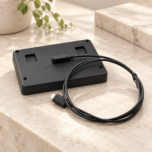
Select conductor size against current, length and the permitted drop and heating. Larger conductors reduce resistance but can make the cable thicker and less flexible, affecting wearables, handheld products and routes that bend close to the enclosure.
Match the opposite termination to the equipment. USB-A or USB-C may suit portable products, while terminals or bare conductors may suit industrial and internal connections. A USB connector shape alone does not establish supported data or charging protocols.
Where the host requires a dedicated termination, review both ends and the conductors as one assembly. Selecting the magnetic head separately can leave important interface requirements unresolved.
Review retention and the mechanical layout
Specify sufficient retention for reliable engagement while preserving the intended removal action.
magnetic mating interfaceInsufficient holding force can allow cable movement to interrupt contact or separate the joint. Excessive retention can pull the device instead of releasing the cable. Test the intended balance with representative hardware and pull directions.
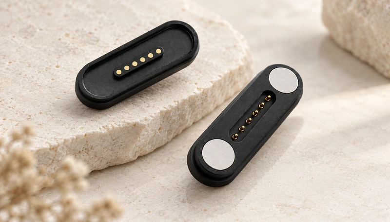
Review retention against device weight, cable direction, interface size, mounting position and operating conditions.
A straight 180° exit can suit available rear clearance. A 90° exit may reduce protrusion and suit side routing on a thin device. These angles describe cable routing, not permission to reverse electrical mating.
Set the installed contact height within the specified working travel. Too little compression may reduce contact stability; too much can increase mechanical stress and wear.
Review board position, housing thickness, contact height and retention as one mechanical arrangement.
Set exposure, life and customization requirements
Choose environmental protection for the expected exposure rather than selecting an IP number in isolation.
Wearables may face sweat and splashes; outdoor products may require dust and water protection. Cleaning fluids and humidity can add finish and corrosion requirements. Ingress ratings alone do not demonstrate performance against every liquid or cleaning regime.
Repeated daily docking places a life requirement on the spring system, finish, exposed surfaces and cable strain relief. Include those parts in the durability review.
spring-loaded contactSet contact-resistance requirements after the specified mating duty as well as for the new assembly.
For an OEM interface, review ten adjustable inputs: contact count, pin assignment, dimensions, retention, cable length, conductor size, exit direction, termination, housing and sealing structure. Confirm which options are available for the selected configuration.
Change the parameters that affect electrical performance, physical fit or use, rather than requiring a custom value for every feature.
Bring the requirements together
A suitable magnetic cable fits the electrical and mechanical requirements of the complete device.
Define supply and signals, allocate contacts, and specify load, cable construction, retention and physical layout. Then set exposure and mating-life requirements for validation.
A standard two- or three-contact cable may suit simple charging. More complex OEM equipment can need a dedicated contact map, cable assembly, orientation or sealing arrangement.
Agreeing these requirements before selection can reduce avoidable redesign. Confirm charging, signals and repeated docking with the representative assembly throughout the required operating duty.