
What Is a Magnetic Cable Connector? From Mating Action to Device Fit
Published on August 25, 2026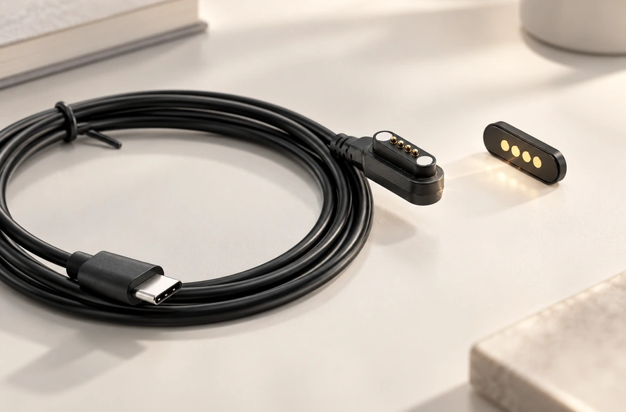
- The complete magnetic cable interface
- The engagement sequence
- Six component roles
- Contact-count options
- Potential docking applications
- Nine selection inputs
A magnetic cable uses magnets to assist mating and conductive contacts to carry the assigned supply or signals. A dedicated layout can suit repeated docking and a small envelope in wearables, medical products, smart devices or industrial equipment, with the requirements validated for each application.
complete magnetic cable interfaceThe complete magnetic cable interface
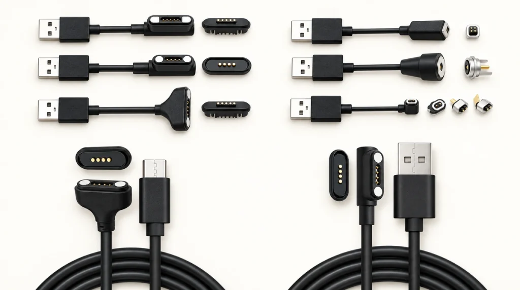
The cable combines a magnetic mating pair with conductors and an opposite-end termination. At the device, magnets and contacts engage the matching interface; the other end may use USB-A, USB-C, terminals, bare conductors or a dedicated connector with defined functions.
USB-A or USB-C ends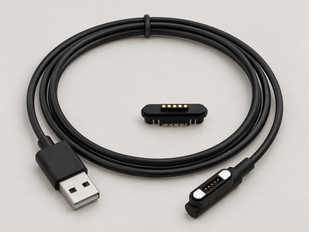
In this architecture, magnets mainly position and retain the joint. Current crosses through conductive contacts and matching pads rather than being transferred wirelessly by magnetic attraction.
The mating action may suit repeated charging or docking without a deep plug-insertion path, where the contact travel, housing and retention meet the device requirements.
Depending on the circuit, assigned functions may include:
Supply and charging paths
The required return or reference path
Defined application signals
Engagement detection
Identification or control functions
Implemented data communication
Specify these functions and their electrical levels for the actual contact map. Contact count offers allocation options, but there is no universal magnetic pinout or protocol implied by it.
The engagement sequence
The mechanism combines magnetic guidance with conductive engagement through spring-loaded contacts.
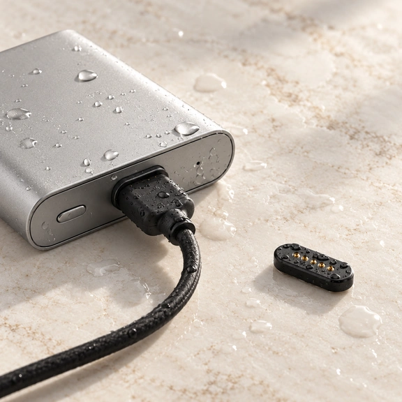
Within the designed capture range, the magnetic pair brings the cable head toward the matching device interface. The housing establishes alignment and the pins compress against their intended pads to complete the defined circuit paths.
A simplified sequence is:
Magnetic attraction → Guided positioning → Spring-contact engagement → Assigned supply or signals
Working travel can accommodate limited axial tolerance between the mating halves. Confirm the installed compression range; spring compliance does not guarantee contact at arbitrary height or lateral displacement.
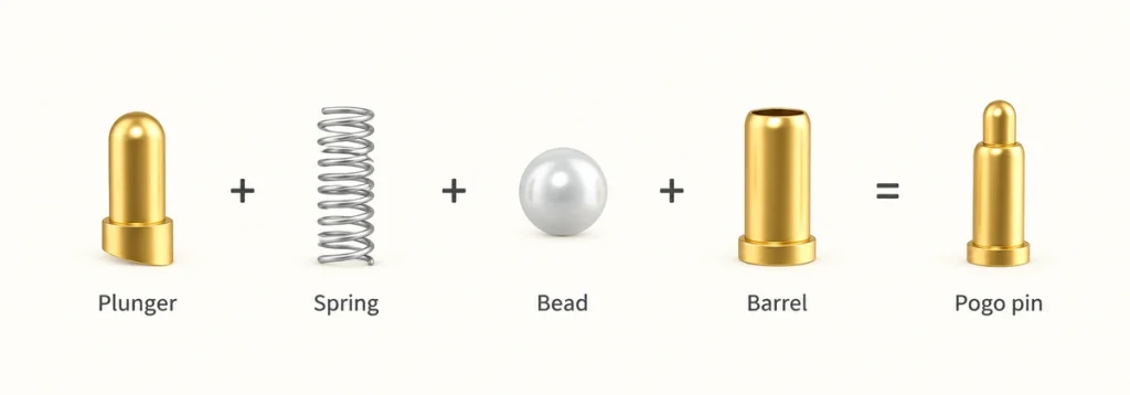
A manufacturer-authored DigiKey explanation describes magnetic spring contacts as an alternative mating approach for power and signals. Its component mechanism is a useful reference, while specific ratings belong to the selected assembly.
magnetic spring-contact mating systemsA sufficient pull can release the magnetic joint. Specify retention and release direction with the cable weight, device orientation, vibration and exposure; controlled removal is not a guarantee against every accidental pull.
Six component roles
The complete interface combines mechanical guidance, conductive paths and cable support.
Mating head: The housing supports the contacts, magnets and insulation and establishes their mechanical position.
Magnets: Attraction assists placement and supplies the defined retention, in combination with housing geometry and spring reaction.
Spring contacts: Compression applies force against matching conductive surfaces within the specified working range.
spring-loaded conductive contactsHousing and insulation: Suitable molded or other insulating structures separate circuit paths and protect the internal construction.
Cable and strain relief: Conductors carry the assigned functions, while the transition structure supports the required bending duty. Validate it rather than assuming unlimited flexing life.
Opposite termination: Select a defined USB-A, USB-C, terminal, bare-conductor or dedicated end for the intended equipment. The form alone does not establish USB data or PD capability.
Length, conductor size, molding, terminations and routing all influence the complete assembly’s electrical and mechanical performance. Evaluate more than the magnetic head.
Contact-count options
Contact count indicates available positions to allocate. Internal connections or parallel paths can reduce the number of independent circuits, and functions still require the actual mapping.
Two-contact magnetic cable
Two contacts may provide supply and return for a compact charging interface where no separate signal path is needed. Verify the load, protection and installed geometry.
An illustrative allocation is:
VCC + GND
Three-contact magnetic cable
A third contact may serve one defined identification, detection, sensing, control or signal function. Implement the corresponding circuitry on both halves.
An illustrative allocation is:
VCC + GND + ID/Signal
Four-contact magnetic cable
Four positions offer additional allocation choices beyond the supply and return.
One possible allocation is:
VCC + GND + Signal 1 + Signal 2
The example may suit charging with basic communication where the conductors, contacts and electronics support the intended interface. It is not a standard USB pinout.
Five-contact magnetic cable
Five positions provide further options for charging with detection, control or communication. Define every function rather than assuming all are automatically present.
Eight-contact magnetic cable
Eight positions can be evaluated where several signals or a mixed supply-and-signal layout is needed. Confirm the required return paths and envelope before choosing the count.
These arrangements are examples. Develop the pinout from current paths, PCB routing, references, signal requirements and the available space, then validate the complete cable and mating pair.
Magtor can review different contact counts and opposite terminations for the required power, charging, signal and identification functions. Confirm the selected configuration and its limits.
Potential docking applications
Consider magnetic cable construction where repeated attachment or a restricted conventional receptacle space creates a defined requirement.
Wearables: Glasses, trackers, compact health products and other wearable devices may need a small contact area. Review load, materials, exposure and charging compatibility for the device.
Medical equipment: Diagnostic or monitoring products, cradles and removable modules may benefit from guided attachment. Device-specific safety, cleaning, materials and regulatory requirements remain separate validation tasks.
Connected home products: Sensors, cameras, panels, pet electronics and rechargeable devices may use a dedicated interface for repeated docking, with the actual functions and protection specified.
Handheld equipment: Scanners, terminals, instruments and portable electronics may use a contact dock for regular recharging. Confirm matching mechanics and charging controls for the intended equipment.
Industrial products: Sensors, fixtures, automation equipment, AGV docks and replaceable modules are possible applications. Evaluate retention, contamination, vibration and contact life under the actual operating conditions.
Docks and cradles: A magnetic cable can provide conductive paths between the device and its desktop charger, base or dedicated fixture. Guided attachment is distinct from induction.
Nine selection inputs
Define electrical functions and mechanical constraints before selecting a mating form or contact count.
Review these nine inputs:
1. Contact count: Identify each independent supply, return, data, detection and control path before deciding the count.
2. Voltage and current: Confirm each contact, conductor and termination for the operating voltage and continuous and peak loads in the complete assembly.
3. Functions: Establish whether the interface carries only charging or also communication, identification, sensing or control, including the required levels and protocols.
4. Length and conductor size: Assess resistance, permitted voltage drop and heating with the actual current. A longer or higher-current cable may need larger conductors.
5. Opposite termination: Select the matching USB-A, USB-C, terminal, bare conductors or dedicated end for the host equipment and its functions.
6. Retention and release: Maintain the required contact compression and engagement while allowing intended removal. Verify loads and pull directions.
7. Exit direction: A 90° exit may suit side routing or limited rear clearance; a 180° exit may suit a straight route. These are cable angles, not proof of reversed electrical mating safety.
8. Exposure: Specify water, sweat, dust and outdoor conditions and review the full sealing structure. Ingress protection does not establish every corrosion, cleaning-fluid or wet-operation requirement.
9. Mating duty: Define the life target and evaluate material, finish, travel, force, contamination and mating geometry under that duty.
For OEM development, review the cable with board position, enclosure dimensions, contact map, load, routing, environment and mating-life target. These inputs determine whether an existing configuration or dedicated design is suitable.
A validated magnetic cable can combine a small contact area with repeated guided attachment and the assigned electrical paths. Start from functions and mechanical constraints, then agree contact count, conductors, retention and terminations for the representative device.