
Magnetic Cable Connector Guide: Designing the Complete Assembly
Published on August 24, 2026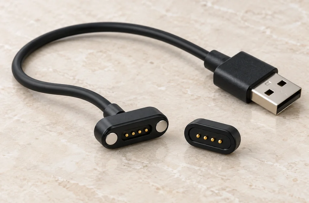
- The magnetic cable as a complete assembly
- Guidance, compression and conduction
- Six parts of the cable assembly
- Choosing the contact count
- Length, conductors and end-to-end mapping
- Selecting the opposite termination
- Validation before production
- Inputs for a dedicated cable design
A magnetic cable assembly combines a guided contact head, conductive spring contacts, cable conductors and a defined opposite termination. Select it as a complete power-and-signal interface: contact functions, wire size, length, retention and validation all need to suit the OEM device.
complete magnetic cable assemblyThe magnetic cable as a complete assembly
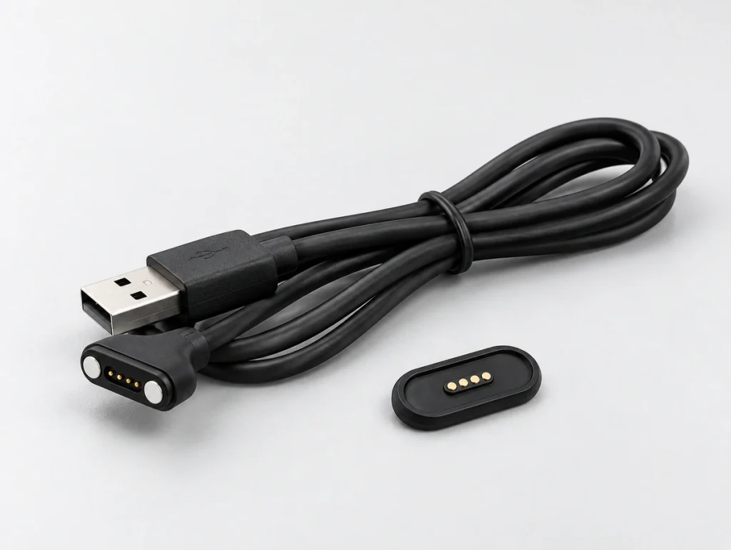
The mating interface typically has a device-side receptacle and a magnetic head on the cable. Select and verify the two as a matching pair.
A typical engagement sequence is:
Magnetic attraction assists placement of the mating pair.
The spring contacts compress against matching surfaces.
The engaged contacts provide the assigned supply, return, data, identification or control paths.
Retention maintains the intended mating state under the defined loads.
A sufficient separating load releases the joint; verify its magnitude and direction.
Guided engagement can assist difficult-to-see docking and avoid conventional plug insertion. Controlled release is another possible feature, with the actual capture range, retention and handling validated for the product.
Distinguish a contact component from a finished cable assembly.
A contact component may contain the magnets and electrical contacts. The complete cable also requires specification of:
Conductors
Insulation
Cable strain relief
Overmolding
Required length
Conductor size
The opposite, source-side termination
For OEM charging or communication, the complete construction determines the interface capability.
Guidance, compression and conduction
Magnets, spring contacts, housing and conductors work together. Electrical continuity requires the appropriate mating position and contact compression.
Magnetic guidance
Attraction brings the matching interfaces toward the intended position.
Magnet placement and polarity can favour the correct direction; housing keying may add control. Validate possible orientations and partial engagement rather than assuming magnets eliminate every incorrect connection.
Select the appropriate retention, not simply the strongest magnet.
Balance the force against:
The connector envelope
Supported device weight
Cable loads and their direction
Handling requirements
Required contact stability
Intended release behaviour
Spring-contact engagement
In the defined mating position, the contacts compress against their targets.
The internal spring loads the plunger against its pad. Correct working travel can accommodate limited axial tolerance between the cable head and device, with lateral alignment and stops set by the housing.
Specify these contact inputs:
Permitted working travel
Installed working height
Force within the working range
Contact resistance
Specified finish
Contact geometry
Insufficient compression may cause intermittent contact.
Excessive compression can increase stress and wear.
Conductive circuit paths
Assign every contact from the device circuit.
Possible functions include:
VCC
GND
Data
ID
Engagement detection
Control
The circuit continues beyond the contact through the termination, conductor, cable and opposite end. Include every part of that route in electrical and thermal assessment.
The allowable load belongs to the complete cable configuration; a contact’s isolated rating cannot substitute for it.
Six parts of the cable assembly
Review the magnetic cable as an integrated mechanical and electrical assembly.
Mating head and housing
The head supports and positions the magnets and conductive contacts.
Possible forms include:
Circular
Oval
Rectangular
A dedicated low-profile form
Choose the mating form from the available enclosure and operating clearances rather than appearance alone.
Compliant conductive contacts
Spring contacts form the mating electrical paths.
Material, finish, force and internal construction influence:
Allowable current
Contact resistance
Resistance to the specified corrosion exposure
Mating-life performance
Electrical continuity under the intended duty
For a Magtor assembly, review the configuration’s allowable current, contact and insulation resistance, and temperature conditions alongside its geometry. Electrical and mechanical requirements need to be agreed together.
Magnets
Magnets provide guidance and retain the joint.
Magnetic design inputs include:
Required magnetic material and grade
Magnet dimensions
Number of magnets
Polarity arrangement
Mating gap
Housing and contact geometry
Magnetic polarity can support orientation control when reviewed with the housing, pinout and circuit protection.
Conductor and cable specification
The cable links the mating head to the power source, controller or other specified electronic equipment.
Define these cable inputs:
Number of conductors
Wire size / AWG
Cable length
Insulation material and requirements
Required shielding
Flexibility and flexing duty
Allowable temperature range
These conductor and jacket details can limit the assembly just as much as the mating contacts.
Strain relief and molded construction
The transition beside the contact head can experience repeated cable bending.
Suitable strain relief can reduce conductor fatigue near the termination. Verify the actual flexing duty rather than treating it as a guarantee against cable failure.
A molded construction may contribute:
Protection of the mechanical transition
The intended external appearance
Sealing where the complete design supports it
A defined cable exit angle
Opposite-end termination
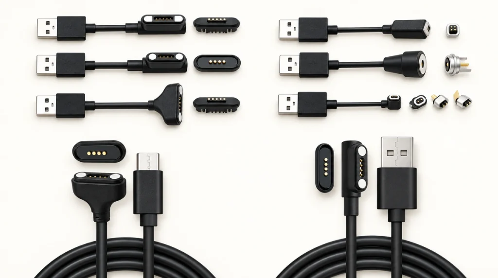
The other end may use:
USB-A
USB-C
Unterminated conductors
A wire terminal
A board-side connector
A dedicated mating connector
Magtor can review magnetic cable configurations with USB-A, USB-C, bare-wire or dedicated ends. Confirm the actual functions and matching interface for the chosen construction.
MagtorChoose the end from the system’s electrical and mechanical architecture.
Choosing the contact count
A contact count does not dictate one universal set of electrical functions.
Identify all independent paths and required returns before selecting the count.
Illustrative allocations are:
| Pin Count | Illustrative allocation | Possible use |
|---|---|---|
| 2 Pin | Power + Ground | A defined supply or charging path |
| 3 Pin | Power + Ground + Signal/ID | Charging with a defined detection function |
| 4 Pin | Power + Ground + 2 Signals | Supply with implemented communication |
| 5 Pin | Power + Ground + multiple signals | Charging with implemented data or control |
| 8 Pin | Multiple power and signal paths | A dedicated multi-function OEM interface |
Scroll horizontally to view every column.
These allocations are examples, not fixed wiring or protocol standards.
Two-contact magnetic cable
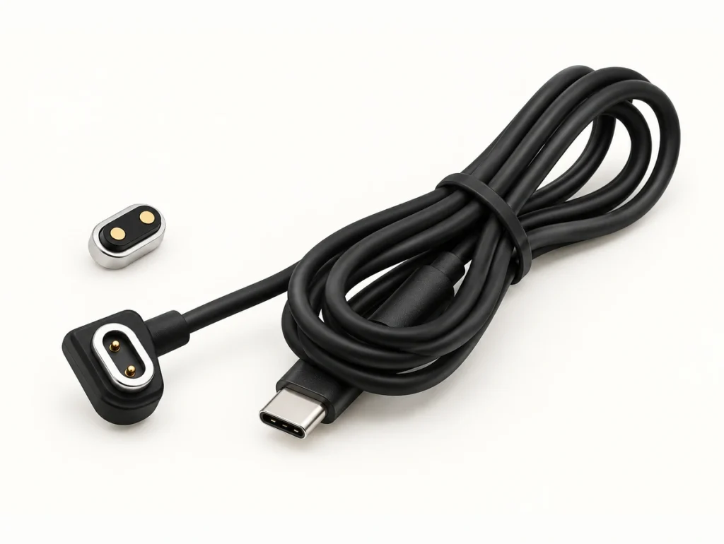
Two contacts may provide a simple supply-only allocation.
One example assigns a positive path and return.
That may suit DC supply or charging where no separate communication path is needed, with the appropriate charging electronics and protection.
Wearables, small chargers and compact rechargeable products are possible uses for that power-only arrangement.
Three-contact magnetic cable
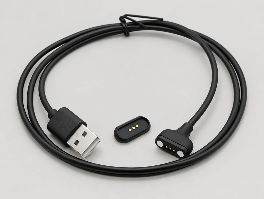
A third path may provide one additional defined function, such as:
Engagement detection
Identification
A temperature-related signal
A defined single-channel communication path
Charging-control signalling
Consider three contacts where the product needs such a function beyond the supply and return. The added path does not inherently increase charging speed.
Four-contact magnetic cable
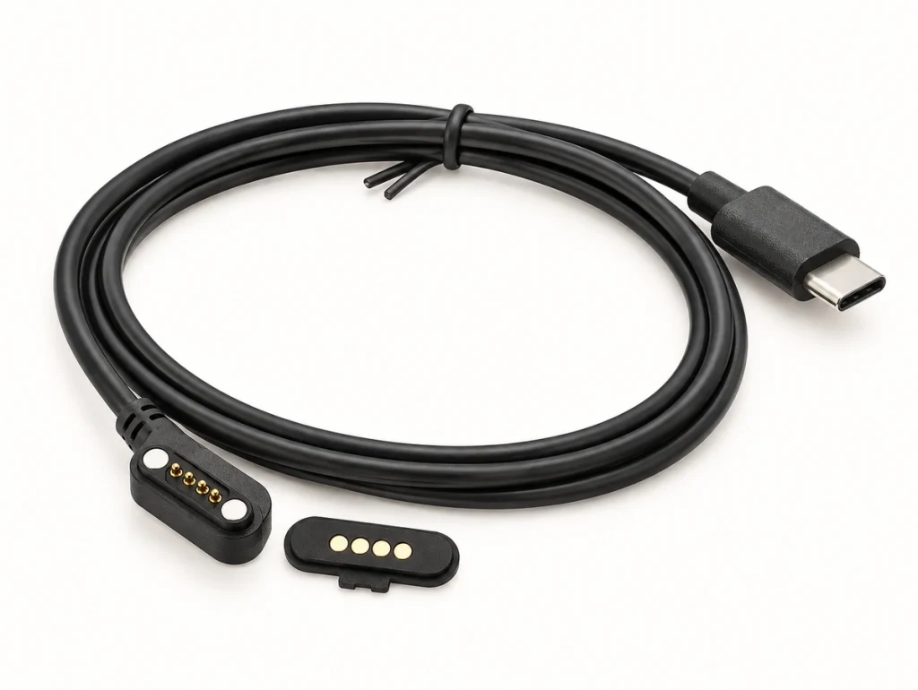
One possible four-path allocation is:
VCC / GND / Data+ / Data−
Confirm that example against the actual drawing; it is not a universal four-contact magnetic wiring rule.
four-contact magnetic interfaceA different device might allocate:
VCC / GND / ID / Control
Magtor’s four-contact wiring discussion explains how the assignment follows the application. Define levels, protocol, numbering and mating views before production.
Keep this distinction explicit:
Contact count alone does not establish a communication protocol.
Five- and eight-contact magnetic cables
Additional paths can accommodate combinations of:
Power
Ground
Several defined signals
Device-identification functions
Sensor paths
Charging-control signals
Implemented communication paths
Supply or return contacts may be paralleled where required. Assess current sharing, contact states, conductors and temperature rise; allowable current does not simply multiply with the contact count.
Choose the number from the circuit map and available envelope together.
Length, conductors and end-to-end mapping
A contact part is only one section of the route. Designing a complete cable requires the length, conductors and both terminations to be assessed together.
Cable length and voltage drop
For otherwise comparable material, cross-section and temperature, increasing conductor length increases resistance.
Evaluate voltage drop using the current and resistance of the path being assessed:
Vdrop = I × R
At low current, the loss may fit within the device’s voltage margin; confirm that margin rather than assuming it is negligible.
At higher current, excessive resistance can cause:
Reduced voltage at the receiving device
Slower charging where the resulting supply condition limits it
Additional cable heating
Greater power loss
Select length with the required current and permitted drop, as well as the routing and handling needs.
Conductor size
Cross-section influences conductor resistance and permissible load in the actual cable and environment.
A higher-current assembly may need larger conductors than a small wearable charging cable. Confirm the complete installed thermal conditions.
Larger conductors also create mechanical trade-offs, which can include:
Greater cable outside diameter
Increased stiffness
A larger termination head
Additional cable loading on a small product
Balance resistance and heating against routing, flexing and device support.
End-to-end contact mapping
Trace every function through the complete route:
Device PCB → Receptacle contact → Magnetic spring-contact interface → Cable conductor → Opposite termination
This mapping is particularly important for dedicated cables with different mating forms at the ends.
Avoid matching numbers without checking the wiring:
Do not assume magnetic contact 1 connects to contact 1 of a USB or board connector. Define the actual conductor mapping and the viewing direction at each end.
Approve the complete wiring drawing before prototype termination.
Initial and aged contact resistance
The magnetic interface adds its own resistance and corresponding voltage drop to that of the conductors.
Its resistance may change with:
Working contact pressure
Wear of the finish
Contamination
Corrosion
Installed working height
The specified mating duty
Measure the relevant resistance changes during reliability validation, including the intended wear and environmental conditions, rather than relying only on the first sample.
Selecting the opposite termination
Choose the opposite end for the actual equipment and its electrical functions, not merely a familiar connector appearance.
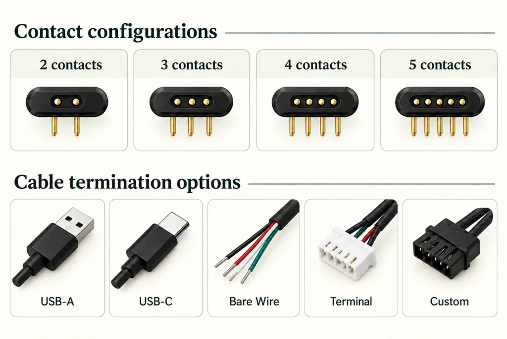
USB-A
USB-A can be considered where the intended equipment uses a compatible conventional port, including:
A compatible charger
A compatible computer interface
A suitable power adapter
Compatible industrial equipment
A compatible USB-A source can serve a basic 5 V charging design. Confirm the source, cable and receiving-device requirements; this does not establish a higher-current or fast-charge capability.
USB-C
USB-C is an option for compatible modern sources and devices. Keep the connector form separate from the functions implemented through it.
A USB-C end does not establish that a magnetic cable supports every USB data mode or USB Power Delivery function.
USB-IF distinguishes the Type-C connector form from implemented data and power capabilities. Confirm the actual conductors, control functions and applicable validation; this interface description is not USB certification.
USB Implementers ForumSpecify whether the USB-C implementation requires:
Basic supply functions
USB 2.0 data
A defined higher-current load
USB Power Delivery
The required CC functions
Other explicitly defined protocol functions
The magnetic end must provide the necessary paths and support the assigned electrical functions as part of that complete implementation.
magnetic contact assemblyBare conductors or terminals
Unterminated conductors may suit:
Prototype work
Internal equipment connections
Test fixtures
A dedicated power supply
Industrial system integration
A matching terminal can simplify installation into the intended equipment. Confirm the conductor preparation and terminal compatibility for the actual connection.
Dedicated opposite-end connector
An OEM interface may call for:
A specified JST-type connector
A board-to-wire interface
Circular connectors
A dedicated board connection
A proprietary mating interface
The cable links two systems with their own functions and constraints. Treat it as an electrical and mechanical interface, rather than only an external accessory.
Validation before production
One successful charging event does not qualify an assembly for production. Validate it against the intended electrical load, duty and exposure.
Set the validation plan from the actual use of the complete cable.
Electrical validation
Relevant measurements may include:
Contact resistance
Cable resistance
Voltage drop
Performance at the specified current load
Temperature rise
Unintended open or short paths
Insulation resistance
Use the expected operating load and representative configuration where appropriate, alongside the required unpowered checks.
Mating-duty validation
Repeated engagement can affect:
Spring-contact components
The contact finish
Magnetic mating surfaces
Housing
The cable strain-relief transition
Cable-flexing validation
Evaluate repeated bending near the connector head under a defined, representative duty.
A contact pair can still conduct while an internal cable conductor is degrading. Check cable fatigue separately from mating-contact performance.
Retention over the required duty
Confirm suitable holding and release behaviour across:
The specified mechanical cycles
The temperature exposures
Permitted assembly-tolerance variation
Representative cable loads and pull directions
Environmental validation
Depending on the application, assess:
The specified salt-spray exposure
Thermal cycling
Humidity exposure
Sweat and relevant chemical exposure
Required vibration duty
Dust exposure
Defined ingress conditions
Magnetic attraction does not itself provide a water seal.
Validate the housing, seals, cable entry, mounting interface and complete enclosure for the required water exposure and mating state.
A magnetic contact cable can form part of a sealed design, but its protection comes from the implemented assembly and test conditions. No single general description establishes an IP result for the finished product.
Inputs for a dedicated cable design
Begin with the device functions and constraints before comparing existing cable forms.
For sample or quotation review, define these inputs:
| Requirement | Specification input |
|---|---|
| Electrical function | Required charging, supply, data, identification or control functions |
| Contact count | 2, 3, 4, 5, 8 or custom |
| Pin assignment | Supply, return and each signal’s defined role and levels |
| Voltage | Maximum operating voltage and required insulation conditions |
| Current | Continuous and peak load currents |
| Cable | Required length, wire size / AWG and materials |
| Termination | The specified USB-A, USB-C, terminal, bare-wire or dedicated end |
| Available envelope | Maximum installation space |
| Retention and removal | Required holding and release force with pull direction |
| Working height | Required working compression at assembly tolerances |
| Cable exit | 90° or 180° |
| Expected exposure | Indoor or outdoor use, sweat, moisture and dust conditions |
| Ingress protection | The required IP test target and assembly state |
| Service-life target | The specified mating-cycle duty |
| Quantity and production stage | Prototype requirements and intended quantity |
Scroll horizontally to view every column.
For a small OEM device, useful mechanical inputs include:
A device 2D drawing
A device 3D model
The PCBA position
Enclosure wall thickness
Available mating-interface space
Required cable exit direction
These inputs let the supplier review the contact assembly against the complete mechanical envelope and tolerance stack.
When another interface may be preferable
Guided attachment can be convenient, but a magnetic cable is not the suitable choice for every system.
Consider a different mating structure where:
The connection must stay mechanically locked against a very high pull load.
Substantial magnetic metal debris can reach the interface.
Universal third-party cable interchangeability is essential.
The system requires a specific standardized industrial connector.
The required high-speed interface cannot be validated with the proposed magnetic construction.
Unintended magnetic release is unacceptable to the device operation.
Choose from the required operating conditions and failure consequences, then assess the available architectures.
Cable-design summary
A magnetic cable assembly integrates magnets, compliant contacts, conductors, housing, strain relief and the opposite termination. Assess that complete construction as the product’s interface.
Two contacts may provide a simple supply and return. Three-, four-, five- or eight-contact examples can allocate additional detection, communication, identification or control functions where implemented by the device.
Review the complete conductive route:
PCB → Magnetic receptacle → Spring-contact mating pair → Cable conductors → External termination
Specify contact count and functions, load, length, wire size, retention, working height and exposure together. The assembled configuration sets the applicable limits.
Early agreement on those requirements can reduce avoidable redesign and support meaningful prototype validation. Confirm the cable in the representative device and operating conditions before production approval.