
Magnetic Pogo Pins and smartphone magnetic wireless charging: Two Different Charging Architectures
Published on August 20, 2026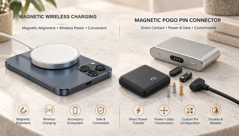
- Conductive contacts and inductive transfer
- How the two architectures operate
- Power and efficiency depend on the system
- Application signals and wireless-control communication
- Wearable, medical and industrial requirements
- Choosing from the device requirements
Both magnetic spring-contact assemblies and smartphone magnetic wireless charging charging use magnets to assist placement. Their power paths differ: conductive contacts carry current in the former, while coupled coils transfer power in the latter. Compare electrical functions, packaging and the complete charging design before selection.
Scope note: Here, magnetic charging primarily means the smartphone magnetic wireless charging system. laptop magnetic contact charging uses conductive charging contacts and is a different architecture.
| Architecture factor | Magnetic spring-contact interface | smartphone magnetic wireless charging |
|---|---|---|
| Magnetic alignment | Yes | Yes |
| Power transfer | Power through conductive mating contacts | Inductive wireless power transfer |
| Exposed mating charging contacts | Yes | No |
| Combined supply and application signals | Yes | Wireless charging-control communication; no freely assigned conductive signal channels |
| Product-specific contact count | Yes | No |
| Product-specific envelope | Yes | Constrained by coil and charging-system requirements |
| Dedicated electrical allocation | Yes | No |
| Sealed-device integration | Possible with a validated complete sealing design | No exposed mating power contacts; enclosure protection remains separate |
| Possible applications | Wearables, medical or industrial devices and dedicated docks | Compatible smartphones and magnetic accessories |
Scroll horizontally to view every column.
Conductive contacts and inductive transfer
The key electrical distinction is the route by which power reaches the receiving device.
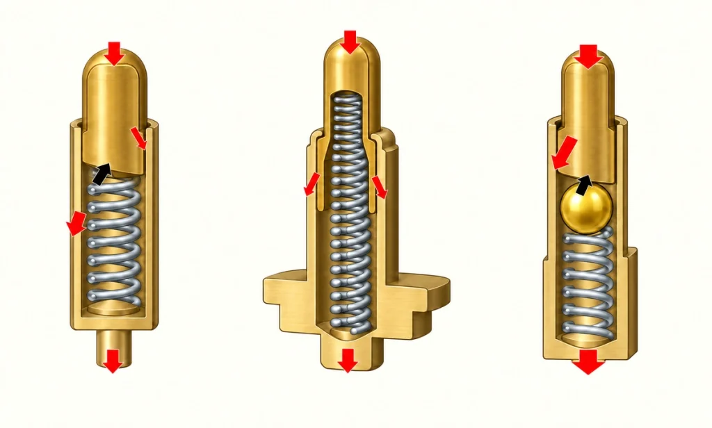
A magnetic pogo-pin pair brings spring contacts into engagement with matching pads. Magnets guide and retain the joint; the contacts form the conductive power or signal paths.
conductive magnetic spring-contact pairSpring compliance allows a contact to accommodate limited variation while operating in its specified travel. A manufacturer-authored guide published by DigiKey explains the component structure and its use in compact, repeatedly connected products. Validate the actual assembly rather than transferring general claims into its rating.
Manufacturer-authored spring-contact explanation at DigiKeyThe reference manufacturer’s smartphone charging guide describes magnetic positioning of a wireless charger against the phone. The magnets assist alignment; induction carries charging power.
The reference manufacturer’s smartphone magnetic wireless charging charging guideThe Wireless Power Consortium likewise distinguishes positioning magnets from power-transfer coils. The coils provide the inductive link, supported by the charging-control electronics.
WPC explanation of magnetic inductionThe conceptual routes are:
Spring-contact interface: Magnet-assisted positioning → Contact engagement → Conductive power transfer
smartphone magnetic wireless charging: Magnet-assisted coil positioning → Inductive power transfer → Device charging electronics
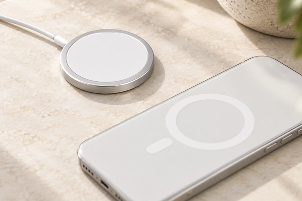
The first is a conductive interconnect; the second is magnetically positioned wireless charging. This distinction concerns the smartphone system within the stated scope.
How the two architectures operate
A conductive magnetic assembly typically combines magnets, spring contacts, matching pads, an insulating housing and a cable or board termination.
Within the designed capture range, magnetic guidance brings the halves toward their mating position. The housing sets alignment and the compressed contacts provide the electrical paths.
A multi-contact layout can provide several functions where the device circuit and interface design support them.
Possible allocations include:
Two contacts may provide a positive supply and return.
A third contact may serve detection or another defined signal.
Four to six contacts may allocate power, signals, identification and data paths.
More contacts offer further allocation options for a defined electrical architecture.
Video material pending replacement
Magtor’s two- through six-contact magnetic assemblies provide different layout options for power and auxiliary functions. Confirm the exact pinout, electrical limits and mating geometry for the selected design.
two-contact magnetic assembliessix-contact magnetic assembliessmartphone magnetic wireless charging charging transfers power without exposed conductive mating power contacts. The magnetic arrangement positions transmitter and receiver coils for the inductive link.
Coil position influences transfer performance. Qi2’s Magnetic Power Profile defines magnetic attachment and alignment for compatible transmitter and receiver designs. Compatibility and certification belong to the actual implemented equipment.
WPC Magnetic Power Profile historyBoth approaches use magnetic guidance, but it supports a different power-transfer architecture in each.
Power and efficiency depend on the system
Evaluate conductive transfer and induction as complete charging systems, with their corresponding conversion and control stages.
For a conductive interface, review the resistance and mechanical conditions along the power route, including:
Contact resistance
Contact diameter
Contact finish
Contact force in the working range
Cable resistance
Current sharing between assigned paths
PCB current-path design
Supply or return contacts may be paralleled where appropriate. Validate current sharing and temperature rise rather than multiplying a single-contact rating by the pin count.
Induction adds a transmitter-to-receiver transfer stage. Coil alignment, separation, temperature and control electronics all affect the resulting efficiency.
Magnetic coil positioning can improve the intended wireless alignment. WPC’s Qi2 announcement discusses that benefit; it is not a measured comparison with a Magtor conductive assembly.
WPC discussion of magnetic alignment in Qi2A conductive magnetic charger is therefore not inherently faster than smartphone magnetic wireless charging charging. Compare actual system limits and operating conditions.
Charging performance comes from the complete power source, interconnect, controls and receiving device.
For smartphone magnetic wireless charging, the device, charger, adapter and operating conditions determine the supported performance. Check the reference manufacturer’s equipment-specific guidance rather than assuming one rating for all combinations.
For spring contacts, allowable current follows the selected electrical, mechanical and thermal design. Pin count alone does not establish it.
A dedicated conductive layout can be useful for a defined DC load, a custom current target or combined power and communication. Determine its suitability from the circuit, packaging and validation requirements.
Application signals and wireless-control communication
A dedicated multi-contact interface allows separate paths to be assigned to the functions the product requires.
Those functions may include:
VCC
Ground
DATA+
DATA-
Connection detection
Device or accessory identification
Charging-control signals
Sensor signalling
Four contacts may allocate supply and signals; five or six can add identification, control or other paths. The required current, signal levels and protocol still need to be designed for the actual interface.
four-contact magnetic assemblyfive-contact magnetic assembly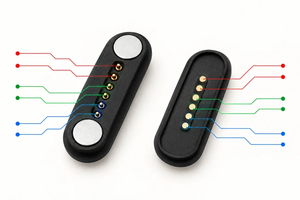
A six-contact Magtor assembly can be reviewed for power, return, data, identification, charging control or sensing. Agree the allocation for the device rather than assuming a universal pinout.
Wireless communication needs a separate distinction:
magnetic charging and Qi systems exchange information needed to control wireless charging and related functions. Supported the reference manufacturer accessories can also use identification features; wireless power does not mean an absence of communication.
That communication is different from a freely allocated conductive interface carrying UART, USB, detection or sensor paths. The smartphone magnetic wireless charging charging surface is not such a general-purpose wired data connector.
the reference manufacturer lists wired USB-C charging and data separately from magnetic charging wireless charging in the equipment specifications examined here. Confirm the particular model’s functions and compatible accessories.
For a product requiring this combination:
Charging + Application data + Engagement detection + Control
a dedicated multi-contact pair may provide the physical paths, with the required circuitry and protocol implemented and validated.
Achievable data performance depends on geometry, conductors, impedance, allocation and signal integrity. Validate the intended interface; extra pins do not automatically provide a protocol or a higher speed.
Wearable, medical and industrial requirements
The appropriate architecture follows the application requirements.
Wearable products
Conductive contacts or induction can be considered for a wearable when the complete design supports the chosen approach.
Induction removes exposed mating power contacts. A conductive pair can instead provide a small dedicated area for power, detection or communication, where the necessary electrical and environmental requirements are met.
A two-contact assembly may suit a power-only interface for compact glasses, trackers, hearing devices or other rechargeable products. Confirm device-specific charging, safety and compatibility requirements rather than assuming a universal replacement charger.
two-contact magnetic pairMedical and healthcare equipment
An equipment dock may need electrical functions beyond charging alone.
Potential dock functions include:
Charging
Identification of the device
Communication
Engagement detection
Service and diagnostic signalling
A multi-contact pair can provide the paths for these functions within a dedicated dock. Medical-device safety, material, cleaning and regulatory requirements still need product-specific validation.
Industrial products
Industrial loads and handling conditions can differ substantially from smartphone charging requirements.
Relevant requirements may include:
The specified current load
Repeated engagement
Guided alignment
Controlled removal
A defined retention target
A suitable dedicated housing
Required signals
Protection for the intended exposure
A dedicated conductive assembly can be developed around those industrial requirements. Compare feasibility and validation with the alternative charging architecture rather than assuming it suits every environment.
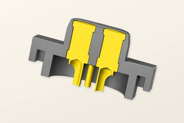
For moisture, dust, sweat or outdoor exposure, review the magnetic contact assembly with the enclosure seals, cable exit and materials. The sealed connector range provides an entry point for that assessment.
sealed magnetic connector rangeRemoving exposed mating power contacts does not establish a waterproof device. Validate the complete enclosure and specify the relevant mating and operating states for either architecture.
Use this table as an initial design comparison, not a compatibility or approval list:
| Application | Architecture to evaluate |
|---|---|
| Smartphone wireless charging | Compatible magnetic charging or Qi2 wireless equipment |
| Phone magnetic accessories | The supported magnetic charging accessory ecosystem |
| Fitness tracker | Conductive contacts or induction, according to the device |
| AI smart glasses | A dedicated spring-contact pair, where the product requirements support it |
| Hearing device charging dock | A dedicated spring-contact pair, where the product requirements support it |
| Medical handheld equipment | A dedicated spring-contact pair, where the product requirements support it |
| Industrial docking system | A dedicated spring-contact pair, where the product requirements support it |
| Robotics | A dedicated spring-contact pair, where the product requirements support it |
| Custom power + signal interface | A dedicated spring-contact pair, where the product requirements support it |
Scroll horizontally to view every column.
Choosing from the device requirements
Compare electrical functions, packaging, environment and handling before selecting the architecture. Familiarity with a technology or brand does not substitute for those requirements.
Consider conductive magnetic contacts for:
A direct conductive supply path
Supply and application signals in one interface
A defined product-specific allocation
Engagement detection or identification
An assembly designed for the specified voltage and current
A compact dedicated envelope
Board or cable integration
Repeated engagement and removal
Defined retention and release behaviour
Integration with a validated sealed enclosure
A power-only design may use two contacts when its electrical and protection needs are met.
Three, four, five or six contacts can offer additional allocation choices where signals are required. Determine the necessary paths and returns before choosing the count.
Three-contact magnetic assembly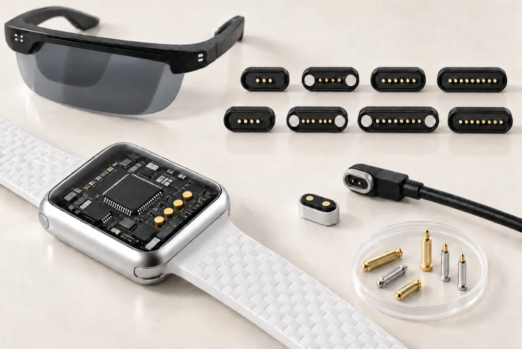
Consider magnetic induction for:
Power transfer without exposed conductive mating contacts
Wireless charging handling
An intended compatible smartphone charging application
Use within a supported magnetic accessory ecosystem
Magnet-assisted transmitter and receiver coil alignment
magnetic charging and Qi2 provide magnetic wireless approaches for compatible consumer equipment. the reference manufacturer describes magnetic charging’s charger positioning, and WPC defines Qi2 MPP alignment. Verify the actual compatibility and certification conditions; these references establish no Magtor approval.
Frame the choice as an interface requirement:
Ask:
Does the product need dedicated conductive power and signal paths, or primarily a compatible wireless charging surface?
A dedicated magnetic assembly may suit a specified combination of power, application signals, detection, sealing, retention, working height and envelope. Review electrical and mechanical feasibility together.
dedicated magnetic contact interfaceWhere contactless smartphone charging and the supported accessory ecosystem are central requirements, evaluate compatible magnetic charging or Qi2 equipment with its specified device, power and operating conditions.
In summary, dedicated magnetic spring contacts offer conductive paths that can be allocated for a product. smartphone magnetic wireless charging uses magnetic positioning for induction and related accessories. Start with power, data, space, exposure and handling, then validate the chosen architecture for the actual device.