
6-Pin Magnetic Connectors: A Practical Design and Selection Guide
Published on August 17, 2026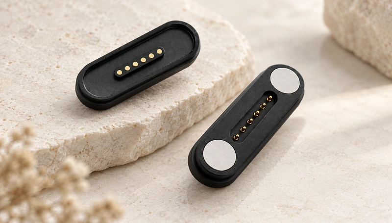
- Understanding the six-contact magnetic interface
- How magnetic engagement works
- Common connection faults and checks
- Potential applications
- RJ12 identification and the interface difference
- Magnetic and conventional connectors compared
A six-contact magnetic assembly can combine power and signal paths with a connection that is easy to attach and remove. Consider it where the product needs frequent docking or a dedicated contact layout. Magtor can discuss the matching connector, cable and pinout for the application; durability and electrical performance depend on the selected configuration.
Understanding the six-contact magnetic interface
This interface uses six conductive contacts and magnetic guidance between matching halves. The magnets assist positioning and retention, while the contacts carry the assigned power or signals. Charging, data and auxiliary functions require a compatible pinout and circuit design.
six-contact magnetic assemblyVideo material pending replacement
Design and construction
A typical assembly combines six contacts, magnets and a supporting housing. Guidance can reduce the alignment effort, but the housing still needs to control final position and working compression. Contact material, finish and mechanical tolerances determine the suitable operating conditions.
Potential design benefits include:
Guided alignment: Magnets help bring the halves into the intended mating position within a defined capture range.
Repeated engagement: Controlled attachment and removal can reduce conventional plug-insertion wear; verify contact life and cable strain relief for the actual duty.
Electrical continuity: Correct alignment, compression and an appropriate contact design support the assigned power and signal paths.
Maintenance note: Remove contamination using the connector manufacturer’s approved method with power disconnected. Debris can impair alignment or contact pressure; cleaning does not restore worn or damaged components.
How magnetic engagement works
The magnetic pair attracts the mating halves and holds them in the designed position. The six contacts then connect their corresponding circuit paths. Check housing alignment, pin assignment and contact travel; magnetic attraction alone cannot prevent every mating error.
Video material pending replacement
Video guide: The example shows magnetic engagement. Use the accompanying discussion to understand the mechanism rather than treating the demonstration as a performance test for every six-contact design.
The engagement sequence
A typical sequence is:
Magnetic attraction: Magnets in the matching halves guide them toward the mating position.
Contact positioning: The housing and magnetic layout bring each of the six contacts to its matching surface.
Electrical connection: The engaged contacts carry the power and signals assigned by the circuit design.
Removal: A sufficient separating load releases the magnetic joint. Validate the force and direction against the device and cable support.
The main components have different roles:
| Component | Function |
|---|---|
| Magnet | Assists positioning and retains the mating pair |
| Pogo Pin | Carries the assigned power or signals at the specified contact compression |
| Protective Casing | Supports and protects the contact assembly |
Scroll horizontally to view every column.
Pinout check: Confirm the contact mapping, viewing direction and electrical functions on both halves before applying power. Matching contact count does not establish compatibility.
Common connection faults and checks
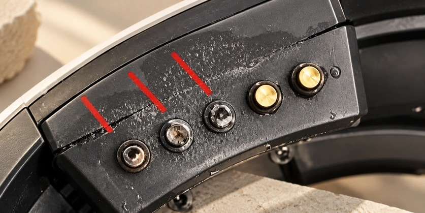
Contamination, inadequate retention, contact wear and corrosion can all cause unreliable engagement. Inspection and an appropriate maintenance method can help identify the cause, while damaged parts may require replacement with a matching assembly.
Troubleshooting checks
- Fault: Contaminated mating surfaces
Possible cause: Dust or other debris on the contact surfaces.
Check: With power disconnected, use an approved dry-cloth or air-cleaning method and inspect for remaining contamination.
- Fault: Inadequate magnetic retention
Possible cause: Inadequate magnetic retention, physical damage or an unsuitable magnetic circuit.
Check: Inspect the mating surfaces and magnetic arrangement. Replace damaged matching parts where necessary rather than assuming every retention fault is age-related demagnetisation.
- Fault: Degraded contact surfaces
Possible cause: Corrosion or worn contact surfaces.
Check: Inspect the finish and working compression. A suitable gold-plated contact may improve corrosion and wear performance, but material selection does not repair an already degraded assembly.
suitable gold-plated contacts
Potential applications
Six contacts can provide separate power and signal functions in a detachable interface. Medical equipment, consumer products, robotics and industrial devices are possible applications, with the actual electrical, safety and environmental requirements assessed for each product.
Application examples
Medical equipment: A guided connection may suit regularly connected equipment. Validate device-specific safety, handling and compatibility requirements.
Consumer electronics: Charging and synchronization are possible where the product supports the assigned power and data functions.
Robotics: A dedicated magnetic interface can support interchangeable modules when contact assignments and retention suit the application.
Industrial equipment: Frequently disconnected assemblies may benefit from guided attachment, subject to their load, life and exposure requirements.
Current check: Specify continuous and peak loads, then assess resistance, cable capacity, voltage drop and temperature rise in the installed assembly. Six contacts do not establish a current rating by themselves.
specified current capacityRJ12 identification and the interface difference
RJ12 commonly refers to a six-position, six-contact modular interface used in telephone and other low-speed connections. It uses a plug-and-socket form rather than the magnetic mating action discussed here. Confirm the exact connector and wiring specification for the equipment.
RJ12 modular connectorChecking a modular connector
Use these identification checks together:
Inspect the contact row: A 6P6C modular plug has six populated contacts. Contact colour alone is not a reliable identifier.
Compare the form factor: The six-position modular plug is narrower than the familiar eight-position Ethernet-style modular plug.
eight-position Ethernet-style connectorCheck the conductors: A fully populated six-contact cable can contain six conductors, but inspect the actual cable rather than assuming every position is wired.
Test the mapping: Verify continuity and pin order against the device’s wiring drawing. The connector form does not establish one universal circuit assignment.
Identification note: Six positions with six populated contacts indicate 6P6C construction. RJ11-related cables can populate fewer contacts in a six-position body, so avoid identifying them solely by housing width or an assumed four-contact rule.
RJ11-related modular cableMagnetic and conventional connectors compared
Use this qualitative comparison as a starting point for the actual interface requirements.
| Design factor | Six-contact magnetic interface | Conventional plug-and-socket interface |
| Connection | Guided magnetic engagement | Plug insertion into the matching socket |
| Alignment | Guided by magnets and controlled housing geometry | Controlled by the plug and socket geometry |
| Mechanical insertion | No conventional plug-insertion action; contact compression and retention still apply | Insertion force depends on the selected connector |
| Custom dimensions | Contact and housing dimensions can be tailored | Often selected from a standard mating form |
| Power transmission | Possible with suitable contacts and thermal design | Possible within the selected connector rating |
| Signal transmission | Possible with suitable pinout and signal design | Possible where the selected interface supports the required signals |
| Pin assignment | Can be assigned for the product | Depends on the chosen standard or dedicated interface |
| Frequent docking | Suitable where the specified mating life and retention are validated | Depends on the connector’s mating-life specification |
| Device integration | Dedicated mechanical and electrical integration | Standard or dedicated mating interface, depending on selection |
Scroll horizontally to view every column.
Cost-of-use note: Compare purchase price with the required mating life, maintenance, downtime and replacement arrangement. A longer service life is a design target to verify, not an automatic benefit of magnetic attachment.
magnetic mating interfacesCost inputs and purchasing checks
The broad $1–$30 range sometimes used for six-contact assemblies is only an illustrative budgeting range, without a specified model, quantity or quotation date. Actual pricing depends on materials, dimensions, cable, customization and order conditions; request a configuration-specific quotation.
Review these five purchasing inputs:
Contact material and finish: Select the conductive material and plating for the required resistance, wear and corrosion exposure.
suited to the specified corrosion exposureRetention: Define a magnetic holding force that maintains engagement while allowing the intended removal action.
Compatibility: Confirm contact assignment and electrical functions as well as the mating geometry.
Supplier capability: Ask Magtor or the proposed supplier to confirm the configuration, manufacturing controls and available supporting evidence.
Service terms: Review the actual warranty and replacement terms offered for the agreed assembly.
Purchase note: Evaluate the complete configuration and expected duty when comparing cost. Suitable quality and validation can reduce avoidable replacement or downtime, but no particular saving is guaranteed.
Choosing a matching six-contact assembly
A magnetic six-contact interface can combine guided attachment with dedicated power and signal paths. Define the pinout, load, retention, working travel and environmental conditions before selection. Discuss the connector and cable requirements with Magtor to review a matching design.
MagtorFrequently asked questions
Can a six-contact magnetic connector be waterproof?
It can be incorporated into a sealed assembly, but the result depends on housing seals, installation and the complete device. Specify the required exposure conditions and verify the assembled configuration; magnetic attachment and contact count alone do not establish an IP rating.
What determines the mating-cycle life?
Spring fatigue, contact finish, operating frequency and contamination all affect life. Define the required cycle target and working conditions, then validate the representative assembly for contact resistance and mechanical behaviour over that duty.
Can the interface prevent reverse mating?
Magnet polarity, housing shape and contact layout can help prevent incorrect engagement. Validate the permitted mating orientations and partial-contact states with the electrical design; these features do not automatically eliminate every reversed or shorted connection.
Why can the connection become intermittent?
Check for dirty surfaces, insufficient contact compression, worn plating, inadequate retention, cable damage and misalignment. Inspect both mating halves and the conductors to distinguish a contact-interface fault from a cable or circuit fault.
Can the cable-side assembly be replaced separately?
A detachable cable-side part may be replaceable without changing the device connector. Use an exact matching replacement with the correct geometry, contact mapping, electrical capacity and any required seals; a similar-looking six-contact cable is not sufficient.