
Rechargeable Hearing-Aid Charging: Mechanisms and Contact Design
Published on August 12, 2026
- Three charging arrangements
- Using magnetic spring contacts in a small charger
- Moisture and contact reliability
- Deciding whether four or five contacts are needed
- Comparing four-contact and five-contact layouts
- Custom charging interfaces from Magtor
A rechargeable hearing aid uses its matching case or dock to charge through conductive contacts or an inductive interface. Magnets can assist the positioning of a contact-based design. This guide separates those mechanisms and discusses four-contact and five-contact options for a custom charger, rather than a universal hearing-aid standard.
Three charging arrangements
Three mechanisms to distinguish during the engineering review are:

1. Conductive contact charging
Matching conductive surfaces on the hearing aid and charger form the power path when the device is correctly seated.
hearing aidOticon’s SmartCharger is one published example of contact charging with magnets assisting the device position. That example describes the charger architecture and does not identify Magtor as its supplier.
A contact interface can fit a small wearable, but exposed pads need the maintenance specified by the manufacturer. Oticon and Signia instructions for applicable contact systems call for dry contact cleaning and correct positioning; follow the model’s procedure rather than assuming water, alcohol or live cleaning is permitted.
2. Magnetically aligned contact charging
Magnetic contact charging is a contact-based arrangement with added magnetic positioning, rather than a separate wireless-energy mechanism.
The magnets guide and retain the device. The physical contacts provide the conductive path once it is properly seated.
Phonak’s Virto R Infinio provides a model-specific “snap and charge” example, attaching magnetically at its matching charging points. It does not establish a generic pogo-pin pinout or compatibility with Magtor parts.
A custom design can similarly combine:
Magnetic guidance → correctly compressed spring contacts → assigned power and signal paths
This approach can reduce small-plug handling when a compact device is placed repeatedly in its matching charger. Verify the actual geometry and charging controls.
3. Inductive charging
Induction transfers energy through coupled coils rather than exposed mating power contacts.
Phonak describes Charger Case Go and Life Charger as inductive options for specified Audéo Life devices. Signia’s Motion support material also lists an Inductive Charger II tutorial; compatibility and current regional availability must be checked for the exact device and charger, rather than inferred for every hearing aid.
Induction can avoid exposed power contacts, but it needs suitable coils, alignment, packaging, thermal management and control electronics. The case’s own USB or Qi input is separate from how it charges the hearing aid.
These mechanisms differ as follows:
| Charging Method | Power Transfer | Magnetic Alignment | Exposed Electrical Contacts |
|---|---|---|---|
| Contact Charging | Physical contact | Optional | Yes |
| Magnetic Contact Charging | Physical contact | Yes | Conductive mating surfaces, as specified by the design |
| Inductive Charging | Electromagnetic coupling | Optional | No exposed mating power contacts |
Scroll horizontally to view every column.
Using magnetic spring contacts in a small charger
The limited space in a hearing aid and case can make some conventional plugs difficult to package. Compare the complete interface against the available envelope.
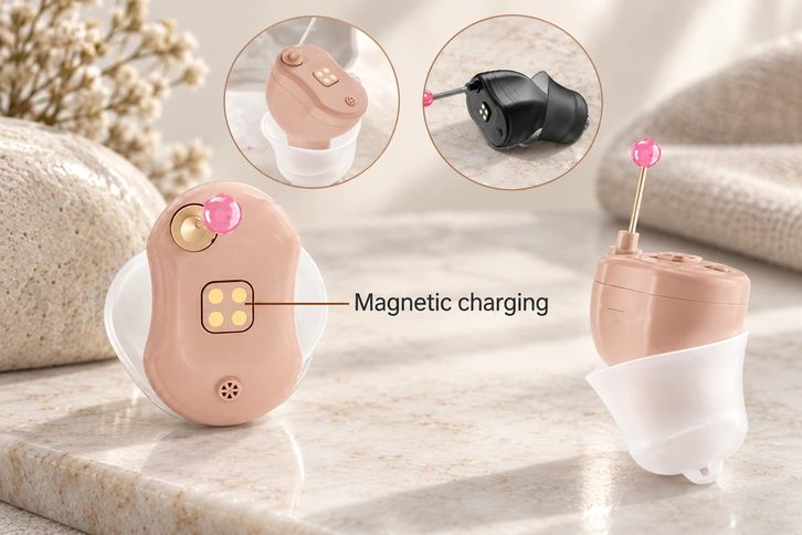
A magnetic spring-contact assembly has two distinct roles:
magnetic spring-contact assemblyMagnets assist positioning and retention; spring contacts conduct electricity.
Within their working travel, spring contacts can accommodate small axial differences in housing dimensions, PCB position and contact height. Charger alignment and lateral positioning still need control.
The intended charging action is:
Place the device → guided alignment → valid contact engagement → charging control permits power
Guided docking can avoid locating and inserting a small plug every day, where the actual case geometry supports it.
Magtor uses magnetic positioning with compliant contacts in custom charging-dock designs. Assess the working height, compression and mating layout for the intended wearable housing.
Set sufficient retention to maintain the contacts while allowing manageable removal. Check the installed force and release direction rather than selecting the strongest magnet.
Moisture and contact reliability
Near the body, exposed contacts may collect moisture, skin residue, dust or other contamination. Include those conditions in the design and maintenance assessment.

For applicable Oticon and Signia contact systems, their instructions emphasise clean pads and correct seating. Use the model-specific dry-cleaning procedure; this guide does not recommend liquid cleaning, immersion or energised cleaning.
For the interface design, review:
Contact resistance
Contact plating
Corrosion resistance
Corrosion resistanceSpring force
Mating-cycle durability
Moisture protection
Housing sealing
Verify initial performance and its change after repeated docking and representative environmental exposure. A satisfactory new contact does not establish long-term reliability.
Small wearable contacts can be sensitive to changes in resistance, wear or contamination. Evaluate charging performance under the defined conditions without treating this as a medical approval claim.
Deciding whether four or five contacts are needed
Four or five contacts are not mandatory for every hearing aid.
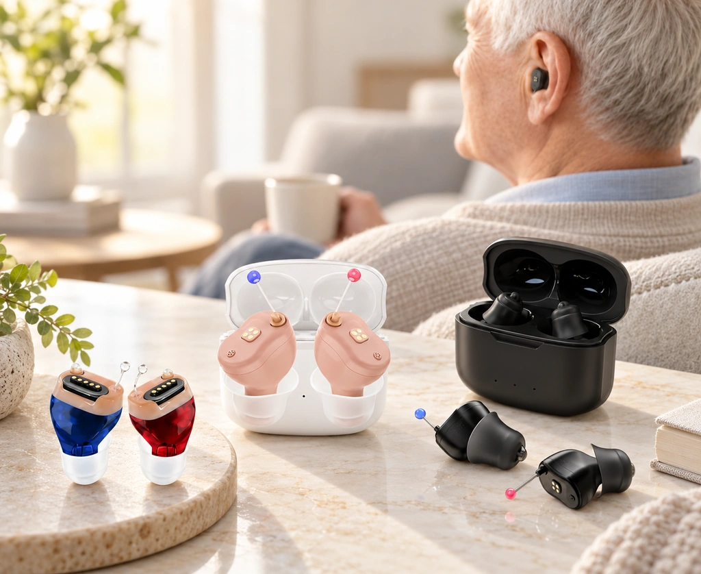
List the electrical functions that must cross between the device and charger.
Charging power alone may need fewer contacts. Detection, identification, control, diagnostics or another signal can require additional conductors according to the circuit and return paths.
A custom four-contact or five-contact interface is one option where those functions require it.
4 Pin Magnetic Connector
4 Pin Magnetic ConnectorOne possible four-contact allocation is:
| Pin | Example Function |
|---|---|
| 1 | Power |
| 2 | Ground |
| 3 | Device Detection |
| 4 | Signal / Control |
Scroll horizontally to view every column.
That allocation can suit power, detection and one basic signal in a compact dock, provided the device’s electrical architecture supports it.
A Magtor four-contact design can be considered for power, ground, detection and a basic signal. Confirm each function and the physical pin positions against the actual device and mating drawings.
5 Pin Magnetic Connector
5 Pin Magnetic ConnectorA fifth contact gives the designer another conductor to assign.
For example:
Power; ground; detection; data; ID or control
That additional contact can serve identification, communication, diagnostics or control where the circuit requires it. It does not automatically supply a complete protocol channel.
Magtor five-contact designs can be reviewed for charging plus an additional data, identification or control path, with the required returns and interface defined.
These allocations are examples, not standardized hearing-aid pinouts. Determine the actual functions, contact positions and protection from the device circuit and charging-system requirements.
Comparing four-contact and five-contact layouts
Choose the contact count from the complete function list rather than assuming that more contacts are better.
| Requirement | 4 Pin | 5 Pin |
|---|---|---|
| Power + Ground | Possible with the required pinout and return | Possible with the required pinout and return |
| Device Detection | Possible | Possible |
| Basic Signal | Depends on the assigned signal and circuit | Depends on the assigned signal and circuit |
| Extra Data / ID Channel | Limited by the remaining assigned contacts | One additional contact to assign |
| Compact Layout | Compare actual footprint and mounting envelope | Compare actual footprint and mounting envelope |
| Basic Smart Charging Dock | Possible where four contacts meet the requirements | Possible where the pinout meets the requirements |
| Advanced Control Functions | Depends on available contacts and control design | Another contact can serve an additional control function |
Scroll horizontally to view every column.
Four contacts may be enough for power, return, detection and one basic signal. This is a function-allocation comparison, not an efficiency measurement.
Consider five when the circuit needs an additional data, identification or control contact.
Also assess:
Available space; contact pitch; working height; current; resistance; retention and release force; finish; environmental requirements
Avoid unnecessary contacts where that saves space and complexity, while retaining every required signal, return and protection function.
Custom charging interfaces from Magtor
Coordinate the interface with the device enclosure, case, PCB and battery architecture. A custom arrangement can be useful when a fixed catalogue connector does not fit those requirements.
Charging interfaces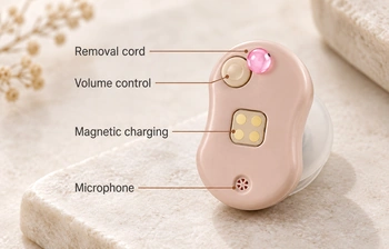
Magtor can discuss four-contact and five-contact magnetic spring interfaces for compact charging docks and wearables. Specify working height, pitch, force targets and electrical functions for the design review; this does not imply compatibility or supply to the named hearing-aid brands.
Project-specific variables include:
Pin count
Pin pitch
Working height
Connector dimensions
Magnetic force
Contact plating
PCB mounting structure
Cable assembly
Environmental protection
Charging-dock geometry
A four-contact dock may cover charging power and basic detection where the complete function allocation permits it.
A five-contact layout offers another assignable conductor where the case needs data, identification or control. Protocol support still comes from the actual electronics and wiring.
Define functions and mechanical space first, then develop and validate the contact assembly around them.
Frequently asked questions
Which mechanisms charge a rechargeable hearing aid?
A rechargeable hearing aid uses a dedicated compatible case or dock. Depending on the design, it charges through conductive contacts, magnetically positioned contacts or induction. Size, battery architecture and charger structure influence the choice.
What do magnets do in contact charging?
In magnetic contact charging, magnets assist the device’s position and retention. Power still crosses through physical mating contacts such as pads or spring contacts; this differs from inductive transfer.
Can a hearing-aid charger use spring contacts?
Yes, when the design meets the required space, working travel, alignment, life and environmental conditions. Spring compliance accommodates limited axial variation and can support repeated docking; it is not unlimited tolerance compensation.
When can four contacts meet the charger requirements?
Four contacts may suit power, ground, detection and a basic signal or control function. Set the actual pinout and physical positions from the device circuit; this is not a universal hearing-aid assignment.
What changes when a fifth contact is added?
A fifth contact gives another conductor for data, identification, diagnostics or control where required. Compare both layouts against the complete pinout, return paths and available space rather than choosing by count alone.
Conclusion
Contact charging, magnetically aligned contacts and induction are all found in the cited manufacturer examples. They illustrate different arrangements rather than a single interface shared by every hearing aid.
A custom dock can use magnetic guidance and spring contacts where compact conductive transfer and manageable placement are useful. Verify the complete mechanism and charging behaviour for the device.
spring-contactChoose four or five contacts only when the device’s electrical function list requires that count. The product category does not prescribe a standard pinout.
Four-contact example: power, ground, detection and one basic signal.
Five-contact example: an additional data, ID or control conductor where needed.
For a custom project, share the available space, circuit architecture, retention and release requirements, and case geometry with Magtor. The interface can then be developed and validated for that application.