
Waterproof Magnetic Connector Design: From Sealing to Electrical Validation
Published on August 10, 2026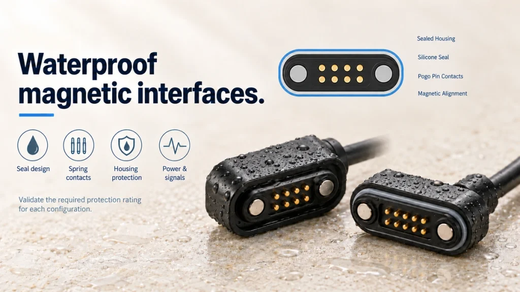
- Defining the sealed magnetic interface
- How the interface connects
- Why an IP rating is only part of the design
- Comparing IP65, IP67 and IP68
- The four main components
- Selecting the contact finish
- Water, contamination and contact resistance
- Assigning the required contacts
- Current capacity and thermal validation
- Balancing retention and release
- Defining service life
- Electrical and environmental tests
- Common failure mechanisms
- Potential applications
- Sealed and standard magnetic interfaces
- Six steps for selecting a design
- Information for a quotation or design review
- Custom design options
A sealed magnetic interface combines guided alignment, spring contacts and a sealing structure. This guide examines how those parts work together in wet or dusty applications, covering IP conditions, contact reliability, testing, service life and selection.
Sealed magnetic interfacesDefining the sealed magnetic interface
A waterproof magnetic connector typically brings together four functions:
Magnets assist alignment and retention of the mating halves.
Spring contacts conduct the assigned charging power, ground, signals or data.
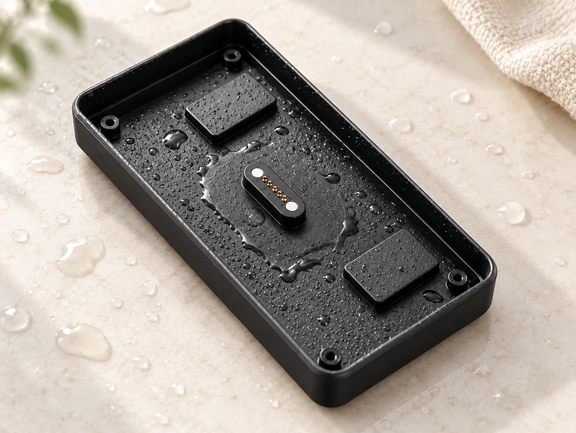
Seals limit water and contamination entering the device through the interface, while exposed contacts require their own environmental assessment.
Mounting features connect the interface to its PCB, enclosure, cable or dock.
Magtor designs combine magnetic guidance and spring contacts with project-specific seals, such as O-rings or insert moulding. The interface is assessed together with the device housing rather than as a separate sealed part.
MagtorMagnetic guidance can reduce conventional plug insertion when the halves approach within the designed capture range. It can suit frequent charging, blind engagement or compact products, but still requires correct alignment, polarity and tolerances.
How the interface connects
The complete pair includes a device-side interface and a matching cable-end or charging-dock half.
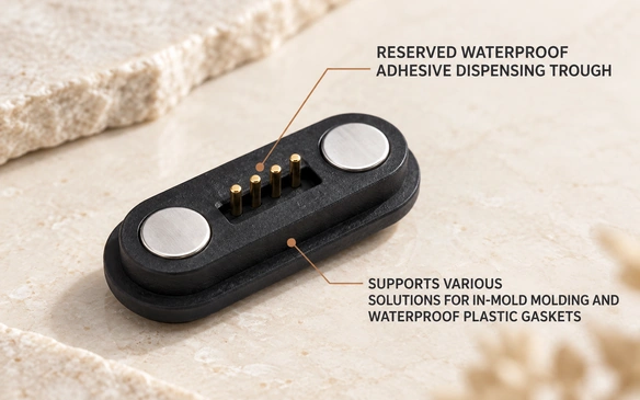
The magnets assist engagement; the compressed spring pins then touch the mating pads and establish the electrical paths. Correct seating and working compression are necessary, and safe power application remains a circuit-design requirement.
The springs supply controlled contact force over their specified working travel. They can support compact, repeatedly mated interfaces when the structure, working height and life requirements are matched; that principle is not itself a verified cycle rating.
Magnetic attraction does not create the water seal.
Depending on the device structure, sealing options include:
O-ring sealing
Sealing grooves
Insert molding
Overmolding
Potting or adhesive sealing
Integrated plastic housing
Panel-to-housing compression seals
Integrate the connector into the enclosure’s sealing system and assess all water paths. A result from an isolated component does not establish the installed device’s protection.
Why an IP rating is only part of the design
Selecting only by the IP number can overlook contact reliability and the actual installation.
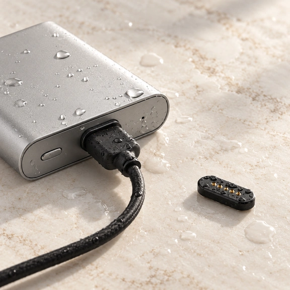
IEC 60529 provides the IP Code framework for enclosure protection against solid objects and water. The rating refers to defined conditions and the tested enclosure configuration.
IEC 60529An ingress test does not establish stable contact resistance for the whole product life. Exposed contacts, wear and the operating environment need a separate assessment.
Address these two requirements separately:
1. Limit water entering the device.
This depends on enclosure seals, mounting, O-rings, moulding, gaps, tolerance control and assembly quality.
2. Maintain the required electrical contact.
This depends on spring force, resistance, finish, contamination, corrosion, mechanical wear and alignment.
spring contactA mechanically sealed interface can still develop electrical faults if its exposed mating surfaces become dirty, worn or corroded.
Evaluate mechanical sealing, electrical contact and environmental exposure together.
Comparing IP65, IP67 and IP68
Set the ingress requirement for the final device and its actual exposure.
| Rating | Protection to assess under the specified test configuration |
|---|---|
| IP65 | Dust-tight protection and the specified water-jet exposure; outdoor conditions may need further tests |
| IP67 | Dust-tight protection and specified temporary immersion |
| IP68 | Dust-tight protection and more demanding immersion under the declared conditions |
Scroll horizontally to view every column.
Check the actual IEC 60529 qualification conditions, particularly the declared immersion conditions for IP68. Products carrying the same label need not have identical depth or duration capability, and immersion qualification does not automatically establish every jet exposure.
For harsh applications, sealing may need to be combined with measures for vibration, temperature, retention and corrosion. These are separate design and test requirements, not consequences guaranteed by an IP label.
The listed standard design range includes IP65–IP67 configurations. Custom Magtor projects can discuss requirements in the IP65–IP68 range, subject to the chosen structure and validation. Confirm the rating and test evidence for the particular installed design.
Select the level needed for the exposure rather than automatically specifying the largest number.
The four main components
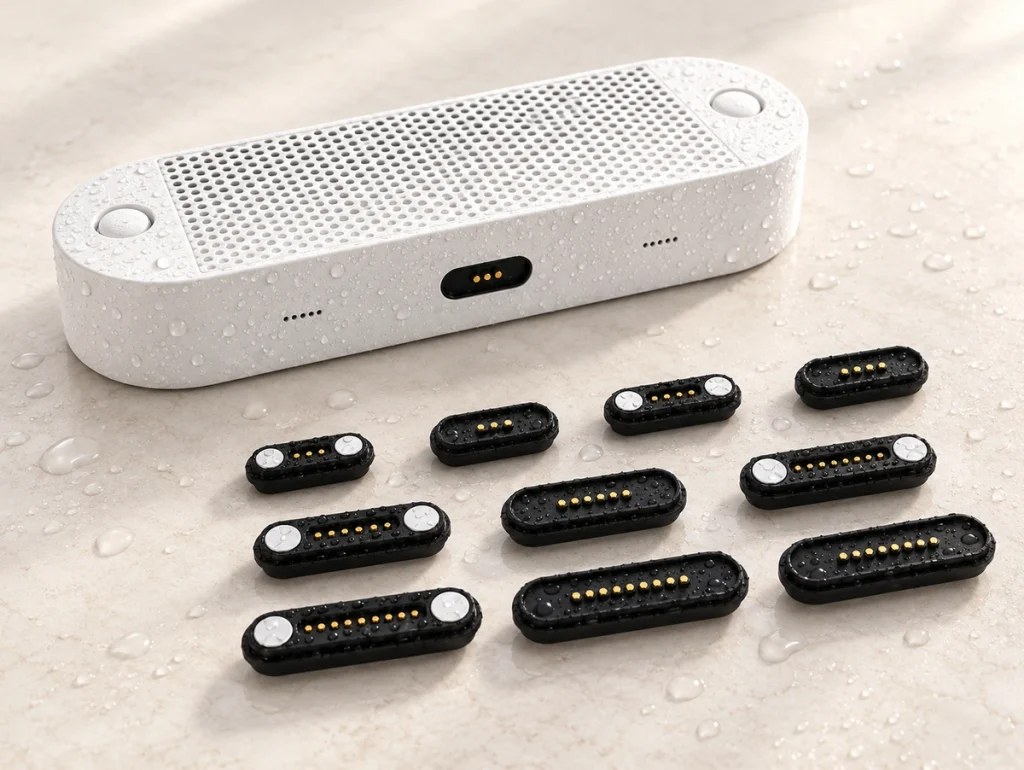
1. Pogo Pin Contacts
A pogo pin typically consists of a plunger, a barrel and an internal spring.
During engagement, the pin compresses within its permitted travel and applies force to the mating surface.
Review these spring-contact parameters:
Working stroke
Spring force
Current capability
Contact resistance
Plunger geometry
Barrel diameter
Plating material
Plating thickness
Expected mating cycles
Insufficient force can produce unstable contact during vibration or contamination. Excessive force can increase wear and assembly stress. Specify the working height and permitted force range rather than compressing the pins to their mechanical limit.
2. Magnets
Magnets assist positioning and retention; they are not the conductive power path.
Magnet geometry and force affect:
Self-alignment distance
User experience
Connection stability
Accidental disconnection force
Connector size
Device-wall thickness
A wearable, industrial terminal and robot dock can require different retention and release behaviour. Specify the requirement for the actual application.
Insufficient retention can allow cable motion or vibration to separate the contacts.
Excessive attraction can make removal difficult and increase housing loads. Measure the installed release behaviour in the relevant directions.
A suitable magnet arrangement can discourage reversed engagement; verify it together with the housing geometry.
3. Sealing Structure
The sealing system must interrupt water paths between the external interface and the electronics. It does not by itself establish corrosion resistance of exposed contacts.
Possible methods include O-rings, grooves, insert moulding, overmoulding, adhesive seals and potting, selected for the actual interfaces and materials.
Review the Magtor connector together with housing geometry, mounting holes, working height, PCB position, seal grooves and cable exit. Those details determine whether the proposed seal can be assembled consistently.
In a thin wearable or compact consumer product, a conventional sealed connector may add thickness or conflict with the industrial design. Compare the complete alternatives against the available envelope.
4. Connector Housing
The housing establishes the positions of:
Pogo pins
Magnets
- PCB
Device enclosure
Waterproof seal
Cable assembly
Control the assembled tolerance stack.
An O-ring can lose the intended compression when housing dimensions, connector height or assembly position vary beyond the design allowance. Review the production tolerances as well as the nominal seal geometry.
Validate ingress protection on the representative assembled device, with its actual mounting and enclosure interfaces.
Selecting the contact finish
Water need not cause immediate failure for it to matter. Over time, corrosion and increasing contact resistance can become the limiting mechanisms.
Exposed contacts may encounter moisture, sweat, salt, dirt, cleaning chemicals and repeated surface wear. Specify the finish for those conditions.
Corrosion can increase resistance, and repeated engagement can wear through a finish. Gold over suitable nickel base layers is one contact-plating approach; the materials, location and thickness must be specified for the application.
A suitable gold finish can help control corrosion and contact resistance during humidity exposure and mating. It does not provide unlimited wear life or make every exposed contact safe to operate wet.
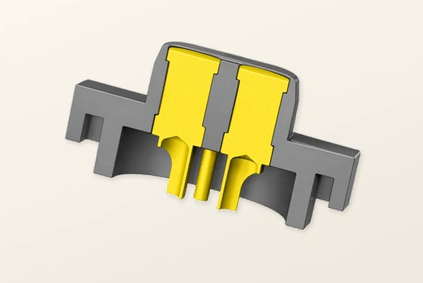
“Gold plated” is not a complete finish specification.
Define at least:
Base material
Nickel barrier layer
Gold thickness
Contact location
Wear area
Mating-cycle requirement
Environmental exposure
A sweaty wearable and a dry indoor dock may need different plating structures and validation conditions.
Water, contamination and contact resistance
Deposits or corrosion can reduce effective conduction at the mating surfaces.
Possible effects include:
Higher contact resistance
Increased voltage drop
Intermittent charging
Heat generation
Signal instability
Charging detection errors
Accelerated corrosion
Measure contact resistance before and after relevant environmental tests, using a defined method and acceptance limits. Ingress testing alone does not reveal every contact-degradation mechanism.
A Magtor validation plan can include resistance, ingress, salt-spray, spring-force, plating-thickness and mating-cycle checks. Agree the scope and request applicable test evidence; this guide does not present a completed model-specific report.
Assigning the required contacts
Assign the electrical functions first, then determine the contact count.
Positive and return may be sufficient for a charging-only path, with charge control and protection provided by the device architecture.
Other contacts can be assigned where required to:
Ground
Charging detection
Device identification
Communication
Temperature sensing
Low-speed signals
Data transmission
Auxiliary power
Magtor offers design families with three, four, five, six, eight and nine contacts, alongside custom layouts. Select the functions and return paths for the actual circuit; the contact count does not establish protocol support.
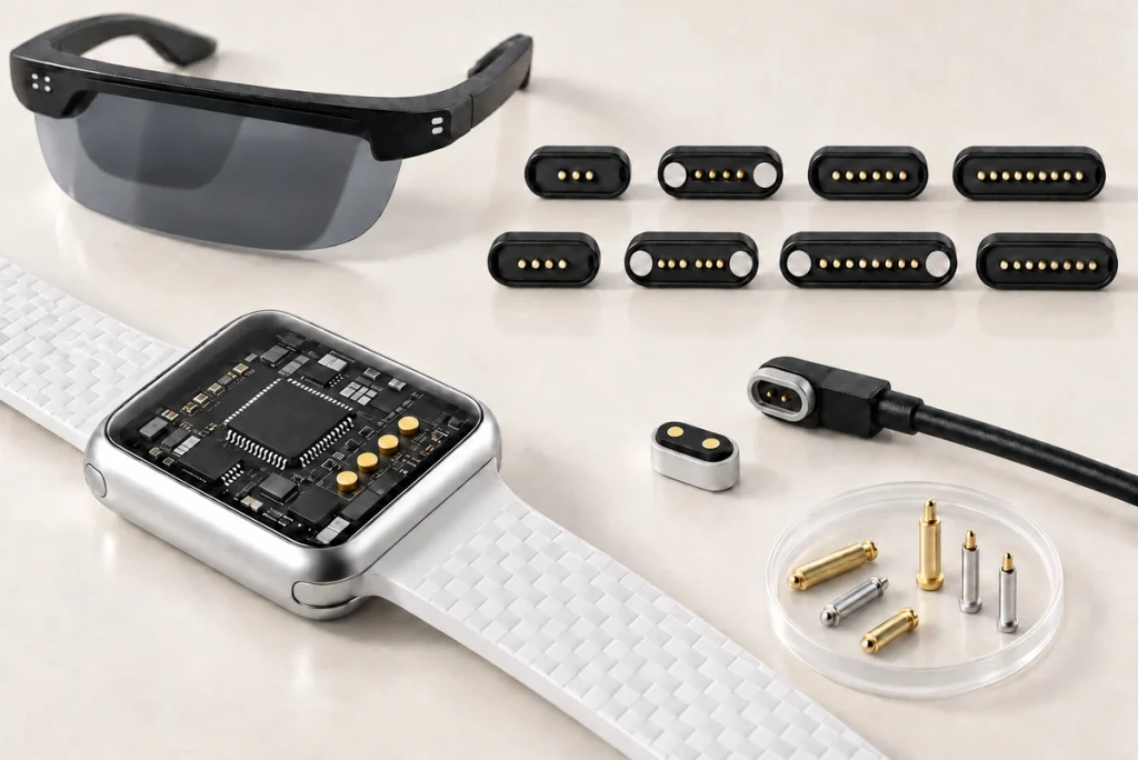
A useful selection rule is:
Use enough contacts for all required functions while retaining adequate spacing, current capability, structural support and sealing space.
Unnecessary contacts can add size, routing, tooling and cost. Compare the actual design rather than assuming a fixed increase per pin.
Current capacity and thermal validation
Current capacity depends on contact dimensions, materials and the conductive path. An IP rating does not determine the allowable current.
Review:
Pin diameter
Contact resistance
Spring design
- Plating
Number of power contacts
PCB copper area
Wire gauge
Ambient temperature
Allowed temperature rise
Mating condition
The listed standard examples generally specify 3 A and, depending on configuration, a 2.0 mm or 2.5 mm pitch. Confirm the model drawing, per-contact and return-path limits, voltage and thermal conditions before applying those figures to a device.
Do not obtain a higher-current interface simply by increasing the supply through an unchanged small contact.
Options can include larger power contacts, parallel conductors, a revised spring structure, larger wires and dedicated signal contacts. Parallel paths require acceptable current sharing and an adequate return path.
Determine the usable current from temperature-rise and voltage-drop measurements in the intended assembly and operating environment.
Balancing retention and release
Provide enough retention for the required contact compression while keeping the intended release action manageable and safe for the whole device.
Consider:
Wearables may prioritise a light attachment and easy removal.
Portable electronics need sufficient retention to avoid unwanted charging interruption.
Industrial terminals may need additional resistance to vibration-induced separation.
Robot docks need a defined capture and alignment range where positioning varies; magnets alone cannot correct unlimited error.
Assess magnetic attraction against the combined spring reaction, seals, friction and actual release direction.
Every contact must stay within its recommended working compression at the assembled tolerance limits.
Defining service life
Assess wear and life across the complete mating system.
Potential wear locations include:
Contact plating
Pogo pin spring
Plunger surface
Contact pads
Housing
Magnets
Cable strain-relief area
A 10,000-complete-cycle target is one reference used for frequent-use spring-contact designs. Treat it as a design or test target until the particular configuration and conditions are documented.
Several listed waterproof configurations state 10,000+ mating cycles. Confirm the applicable model, working travel, electrical load, test method and failure criteria before adopting that figure as a rating.
magnetic interfaceField life also depends on dirt, angle of engagement, current, contact force, cleaning, temperature and the finish specification.
A laboratory count should form part of the life assessment rather than serving as its only criterion.
Electrical and environmental tests
Before production, establish and complete the relevant electrical and environmental validation for the interface.
Waterproof Testing
Check the entire seal arrangement against the required ingress conditions.
Use the actual enclosure or a production-representative assembly wherever practicable.
Contact Resistance Testing
Record initial resistance and its change after the specified mechanical and environmental tests.
An increase can indicate contamination, worn plating, reduced spring force or corrosion. Investigate the cause against the application’s acceptance limits.
Mating-Cycle Testing
Repeatedly connect and separate the pair to examine:
Spring fatigue
Contact wear
Plating degradation
Housing damage
Magnetic alignment
Salt-Spray or Corrosion Testing
This is particularly important for:
Wearables
Outdoor electronics
Marine-related products
Industrial equipment
Devices exposed to human sweat
Spring-Force Testing
Check spring force across the specified working travel against the required limits.
Plating-Thickness Inspection
Inspect the achieved plating thickness at the specified locations with an appropriate measurement and sampling method.
Vibration and Shock Testing
For industrial, robotic, automotive or moving equipment, check that the specified vibration and shock do not produce unacceptable contact interruption.
Harsh-environment validation often combines ingress testing with mechanical checks for vibration, shock and retention. Define each test for the actual application rather than treating sealing as proof of them all.
Common failure mechanisms
Incorrect Housing Integration
A sealed connector can still leave a leakage path at its joint with the device enclosure. Assess that interface too.
Design the seal around the actual production tolerances.
Poor Plating Selection
An unsuitable contact finish may corrode under sweat, humidity, salt or cleaning chemicals. Define those exposures before selecting the plating.
Excessive Plating Wear
Repeated engagement can remove plating, particularly where angled mating introduces extra sliding or scraping.
Misaligned Magnetic Design
Incorrect magnet or housing position can leave spring contacts under-compressed or the mating halves unstable.
Incorrect IP Requirement
An interface qualified for a particular IP67 test can still fail when field exposure exceeds those conditions. Compare the actual environment with the qualification assumptions.
Potential applications
Wearable Devices
Examples include:
Smartwatches
Health trackers
Hearing-related devices
Sports electronics
Wearable medical equipment
A contact-based charger can avoid a conventional exposed socket and simplify frequent charging. Its contact surfaces and enclosure penetrations still require protection.
For a wearable, assess sweat exposure separately from the water-ingress requirement.
Outdoor Electronics
Typical applications include:
GPS trackers
Outdoor sensors
Cameras
Navigation equipment
Shared mobility devices
Rain, dust, humidity and temperature variation may all affect an outdoor interface; specify them separately.
Outdoor electronics are one application area considered by Magtor for sealed magnetic interfaces, with model-specific exposure and validation requirements.
Medical and Healthcare Devices
Portable medical equipment can combine frequent charging with repeated cleaning. Define both requirements for the particular device.
Review materials, cleaning chemicals, mating life, enclosure seals and device-specific safety requirements early. A sealed commercial connector does not establish medical-device compliance.
Industrial Equipment
Factory equipment can be exposed to:
Dust
Oil
Vibration
Water
Cleaning fluids
Repeated operator use
Magnetic guidance can assist quick engagement or reduce manual insertion demands within its designed capture range.
Cleaning Equipment
Robot vacuums, smart mops, cleaning robots and other battery-powered cleaning equipment can expose an interface to both water and cleaning fluids.
A magnetic dock can simplify engagement. Protecting its internal electronics still depends on the complete seal structure and validated installation.
Smart Home Devices
Cameras, smart locks, sensors and control devices may need a compact interface that fits the product’s exterior and internal packaging.
A custom design can adjust housing shape and height, magnet position, contact arrangement and mounting features around that enclosure.
Sealed and standard magnetic interfaces
| Feature | Standard Magnetic Connector | Waterproof Magnetic Connector |
|---|---|---|
| Typical Environment | Typically intended for the specified dry exposure | Designed and tested for the specified wet, dusty or corrosive exposure |
| Sealing Structure | As required for the intended dry application | O-ring, molding, potting or sealing groove |
| Housing Integration | Depends on the actual mounting and enclosure | Seal interfaces must match the enclosure |
| Corrosion Requirement | Set from the dry application’s actual exposure | Set separately for the actual wet, sweat or salt exposure |
| Plating Requirement | Application dependent | Often optimized for environmental exposure |
| Validation | Electrical and mechanical; relevant environment still assessed | Electrical, mechanical and defined environmental tests |
| Cost | Depends on materials, tooling and supply scope | Added seals or controls may increase cost |
| Customization | Project-dependent | Often needs application-specific seal and housing design |
Scroll horizontally to view every column.
A standard Magtor interface can suit its specified dry environment. A sealed version adds the required sealing structure and enclosure integration; select and validate the actual configuration rather than relying only on its category name.
Additional sealing is useful when ingress is a real risk. In a dry product, unnecessary seals may add space, cost or complexity, so assess the actual exposure before specifying them.
Six steps for selecting a design
Begin with the application requirements, then compare suitable designs.
1. Define the Environment
Determine whether the connector will encounter:
Sweat
Rain
Temporary immersion
Continuous moisture
Dust
Salt
Oil
Cleaning chemicals
Vibration
Set water-ingress and corrosion requirements separately.
2. Define the Electrical Requirements
Provide:
Operating voltage
Charging current
Pin definition
Signal requirements
Data requirements
Ground requirements
3. Define the Mechanical Space
Specify:
Available length and width
Connector height
PCB location
Housing wall thickness
Mounting holes
Cable direction
4. Define the Required Service Life
Estimate complete mating cycles over the intended service life, with the relevant operating conditions.
5. Define the Sealing Strategy
Choose an O-ring, moulded seal, potting, enclosure-compression seal or another method to suit the device’s materials and structure.
6. Validate With the Actual Device
Before production release, evaluate prototypes in a representative production enclosure.
This stage should expose compression, tolerance, assembly, alignment, leakage and contact problems before committing to tooling or larger production volumes.
Information for a quotation or design review
Complete requirements at the beginning give the design review a better basis and can reduce avoidable iterations.
Provide:
Application: Identify the product, such as a wearable, outdoor sensor, medical device, robot or charging dock.
Contact count and pinout: Assign each power, ground, signal and data function.
Voltage and current: State continuous operating conditions and peak requirements separately.
Ingress requirement: Specify the required IP65, IP67 or IP68 conditions where applicable.
Environment: Describe water, sweat, dust, salt, cleaning agents, oil, vibration and temperature exposure.
Installation envelope: Supply the available dimensions or an enclosure drawing.
Life target: State the expected complete mating cycles and service conditions.
Cable: Specify length, conductor size, termination and exit direction.
Production quantity: Estimate volume to support tooling and process selection.
For custom Magtor projects, the review can progress through drawings, structural recommendations, sample approval, validation and production release. Sample approval does not replace the agreed environmental or reliability tests.
Custom design options
Yes. An OEM interface can be developed around the product when a catalogue part does not meet the requirements.
Variables to discuss include:
Pin count
Pin definition
Connector dimensions
Pin pitch
Pogo pin diameter
Magnetic force
Magnet layout
Working height
Housing shape
Mounting method
Waterproof structure
Contact plating
Cable length
Cable outlet direction
Current capability
A custom spring-contact interface can offer useful packaging flexibility, subject to the final design and validation.
Magtor can review contact allocation, magnet force, housing dimensions, mounting, cable assembly, seal method, electrical requirements and plating against the OEM specification. Confirm feasibility and validation for the proposed combination.
Conclusion
The word “waterproof” needs a defined test condition and installed sealing structure behind it.
Coordinate spring contacts, magnetic alignment, plating, seals, enclosure, PCB layout, cable and production tolerances to achieve the required performance.
Evaluate the connector in the complete device throughout selection and validation.
Define exposure, electrical functions, contact count, life target, space and ingress requirements first. Use those inputs to set contact force, plating, retention and the enclosure seals.
With appropriate design and validation, a sealed magnetic interface can suit wearables, medical equipment, outdoor electronics, industrial and cleaning products, smart-home devices or charging docks. Each application still needs its own safety and environmental assessment.
Where a standard part cannot meet the enclosure or electrical needs, a custom design can develop dimensions, contact layout, seals, force and cable assembly around the product’s actual constraints.
Frequently asked questions
Can a magnetic interface be waterproof?
A magnetic contact assembly can form part of a waterproof device, provided the complete sealing arrangement meets the stated test conditions. O-rings, moulding, potting, enclosure tolerances, mounting and assembly quality all matter. IEC 60529 supplies the classification framework; it does not certify this particular design.
Can a sealed magnetic interface carry power and data?
Yes, where contacts are assigned to power, ground, detection, communication and data as the circuit requires. Available PCB space, current and signal requirements determine the count and layout. Magtor multi-contact designs can be considered with those functions and return paths defined.
Should every design specify IP68?
No. Specify ingress protection from the actual exposure and confirm the qualification conditions. More demanding sealing can add structure, assembly controls, space and cost, so the highest label is not automatically the most suitable.
How should I interpret the stated cycle life?
Some listed standard configurations state 10,000+ complete mating cycles. Verify the particular model and test evidence. Plating, spring force, contamination, current load, angle and environment determine whether that result applies to the device.
Why can a sealed interface lose charging contact?
Check corrosion, contamination, insufficient compression, worn plating, misalignment and rising resistance. A seal can protect the interior while exposed electrical contacts still degrade; assess their finish and working force separately.
What information is needed for a custom sealed interface?
Send the application, device drawing or available envelope, contact count and functions, voltage and current, ingress conditions, environment, cycle target, cable requirements and estimated volume. These inputs support a seal and contact design for the actual product.