
Five-pin Magnetic Wiring: Assignments, Views and Validation
Published on August 3, 2026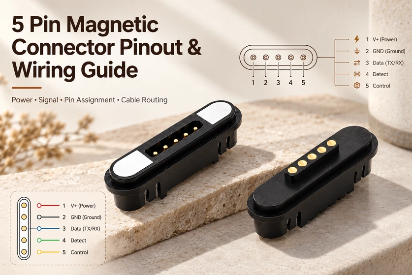
- What the Contact Assignment Defines
- Six Example Wiring Arrangements
- An Example Power-and-data Layout
- Documenting Both Mating Views
- Current Paths and Contact Heating
- Signal Routing and Stability
- Detection and Power-control Timing
- Choosing a 90° or 180° Cable Exit
- Board and Housing Integration
- Sealing the Rear and Cable Exit
- Designing Against Corrosion
- Documenting Cable Colors
- Prototype Verification
- Application Examples
- Inputs for a Custom Cable Drawing
A five-contact magnetic interface can combine charging, data, detection and control. This guide covers example assignments, mapping between mating halves, power and signal routing, 90° and 180° cable exits, sealing and the tests needed before sample approval and production.
5 pin magnetic connectorWhat the Contact Assignment Defines
A pinout assigns an electrical role to each contact. Similar-looking five-contact parts can be wired differently, so external appearance does not establish compatibility.
One project may use the five pins for:
Pin 1: Power
Pin 2: Ground
Pin 3: Data+
Pin 4: Data-
Pin 5: Device Detection
Another device may use:
Pin 1: Power
Pin 2: Ground
Pin 3: Transmit Signal
Pin 4: Receive Signal
Pin 5: Identification or Control
For charging only, a design may use parallel power or return contacts according to its current and space requirements. Evaluate current sharing and the entire supply-and-return path.
Do not copy the colors or contact order of an unrelated cable. Before assembling samples, agree the mating-face drawing, wire definitions, PCB layout and electrical schematic for the actual pair.
Six Example Wiring Arrangements
These arrangements illustrate engineering options; none is a mandatory five-pin standard.
| Configuration | Typical Pin Assignment | Suitable Applications |
|---|---|---|
| Charging and USB-style data | VBUS, GND, D+, D−, Detection | Handheld devices, smart accessories and charging docks |
| Power and control signal | V+, GND, Signal 1, Signal 2, ID | Industrial modules, smart home devices and sensors |
| Charging and device identification | V+, GND, Detect, ID, Control | Wearables, medical electronics and dedicated chargers |
| Dual power contact design | V+, V+, GND, Signal, Detect | Devices requiring more contact area for power transmission |
| Dual ground contact design | V+, GND, GND, Data, Detect | Noise-sensitive or mechanically constrained devices |
| Sensor interface | V+, GND, Data, Clock, Detect | Sensor modules and removable electronic assemblies |
Scroll horizontally to view every column.
Let the device requirements determine the contact assignment. Establish these inputs before allocating the five contacts:
Required charging current and voltage
Signal protocol and data rate
Whether hot plugging is allowed
Whether device detection is needed
Available PCB space
Contact sequence during mating
Cable wire gauge and shielding
Waterproof and corrosion requirements
An Example Power-and-data Layout
For a low-voltage product with charging and basic communication, the following is one possible layout:
| Pin | Suggested Function | Design Consideration |
|---|---|---|
| Pin 1 | Power input | Select contact size according to current and temperature rise |
| Pin 2 | Ground | Keep the return path short and adequately sized |
| Pin 3 | Data or signal 1 | Route away from noisy power circuits where possible |
| Pin 4 | Data or signal 2 | Use as a differential pair when required by the protocol |
| Pin 5 | Detection, ID or control | Can be used to identify connection before enabling power |
Scroll horizontally to view every column.
With the appropriate circuit, this compact layout can provide charging, communication and detection through the same interface.
Set the physical contact order with return paths and noise in mind. Closely adjacent power and signal contacts without a suitable return can expose communication to charging-switch noise. A center ground or a ground between power and signal contacts is an option for sensitive signals, subject to the complete layout and protocol.
Documenting Both Mating Views
A change of viewing direction between the two connector drawings can lead to a wiring error.
For example, copying an order shown at the device mating face onto a cable-side rear or solder-side view can reverse contacts 1 and 5. The actual mapping depends on both viewing directions and the keying geometry.
Every drawing should clearly indicate:
Mating-face view or rear view
Male-side contact numbering
Female-side contact numbering
Cable wire colors
Magnet polarity
Connector orientation mark
PCB pad numbering
Use a drawing note that defines the relevant views, for example:
Contact numbers refer to the specified mating-face view. Map the cable-side contacts to the complementary mating arrangement using the defined views, orientation marks and contact-to-net drawing.
Before applying power, check continuity and unintended shorts with the circuit isolated. Confirm the approved mapping between the mating halves.
Current Paths and Contact Heating
Five contacts do not define a current rating. Contact diameter and material, spring force, travel, resistance, plating, wire gauge, PCB copper and ambient temperature all contribute to the complete path’s limit.
pogo pinThe power loss at a contact can be estimated using:
Power loss = Current² × Contact resistance
A small resistance increase can produce significant heating at higher current. Contamination, insufficient compression, worn plating or misalignment can increase that resistance further.
During development, engineers should test:
Contact resistance before and after mating-cycle testing
Connector temperature under continuous load
Temperature at the solder joint and cable outlet
Voltage drop across the complete cable assembly
Performance at minimum and maximum working stroke
Behavior after salt-spray or humidity exposure
Parallel power or return contacts can add current-carrying area, but unequal resistance can produce uneven current sharing. Verify temperature rise and voltage drop through the complete circuit, including any single-contact return path.
Signal Routing and Stability
Low-speed communication, detection, sensing and control are possible five-contact functions. Higher-speed communication needs a more detailed interface and signal-integrity assessment.
Signal performance is influenced by:
Pin spacing
Ground-return location
Cable length
Wire twisting or shielding
Connector geometry
Contact resistance variation
Cable routing near power circuits
Mating movement and vibration
Give a differential pair appropriately matched electrical paths and controlled cable routing for its protocol. Its ground reference must not rely on an undersized or intermittent contact.
Communication on an open bench does not establish installed performance. Test the sample inside its intended enclosure with the specified cable length, charger, PCB and firmware.
PCBDetection and Power-control Timing
The fifth contact can be allocated to device detection, charger or accessory identification, temperature sensing or power-enable control. Its role comes from the device architecture.
A detection pin can help the system:
Confirm that the connector is fully seated
Enable the charging circuit after stable contact is established
Disable power before disconnection
Identify an approved cable or accessory
Switch the device into docking mode
Monitor a thermistor or other sensor
Large input capacitors and frequent hot plugging make controlled enabling particularly relevant. Instead of energizing the interface at the first touch, a suitable circuit can detect mating and apply power after a defined delay. Debounce, inrush and sequencing still need validation.
Different contact heights can help control the mating sequence, subject to mechanical tolerances and test results. A longer detection pin can touch first before the main contacts seat, but it commonly separates later; it does not by itself ensure that power is disabled before separation.
Choosing a 90° or 180° Cable Exit
A 90° exit and a 180° exit may use the same electrical contact assignment. The primary distinction is cable routing and its associated mechanical geometry.
90° 5 Pin Magnetic Data Cable
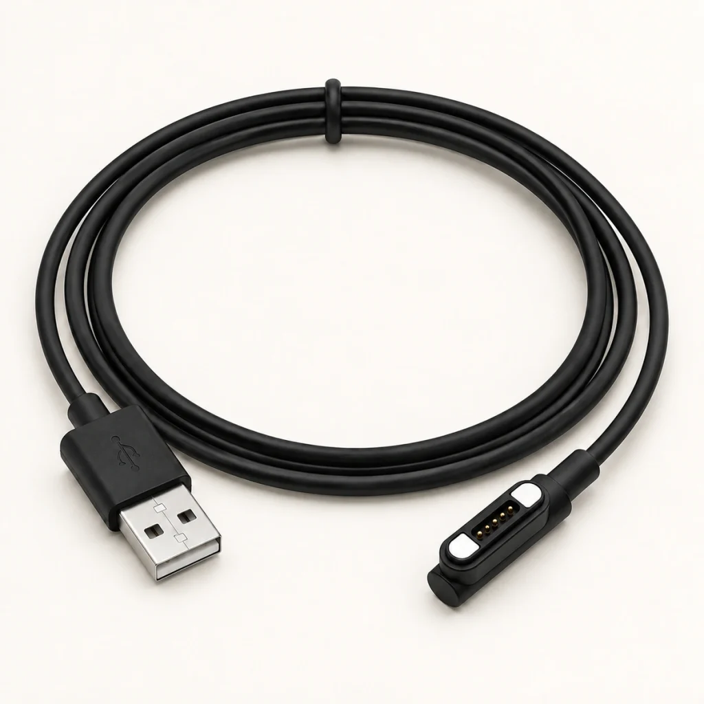
A side-entry exit, described here as 90°, may suit a cable that must stay near the enclosure or where straight routing has insufficient rear clearance. Confirm the angle convention on the approved drawing.
Common applications include:
Wearable charging equipment
Side-mounted industrial controllers
Medical electronics
Compact handheld devices
Devices installed against a wall or panel
Allow for overmold dimensions, bend radius, pull direction and strain relief. A side exit can reduce a bend directly behind the head, but an unsuitable orientation can introduce rotational load.
180° 5 Pin Magnetic Data Cable
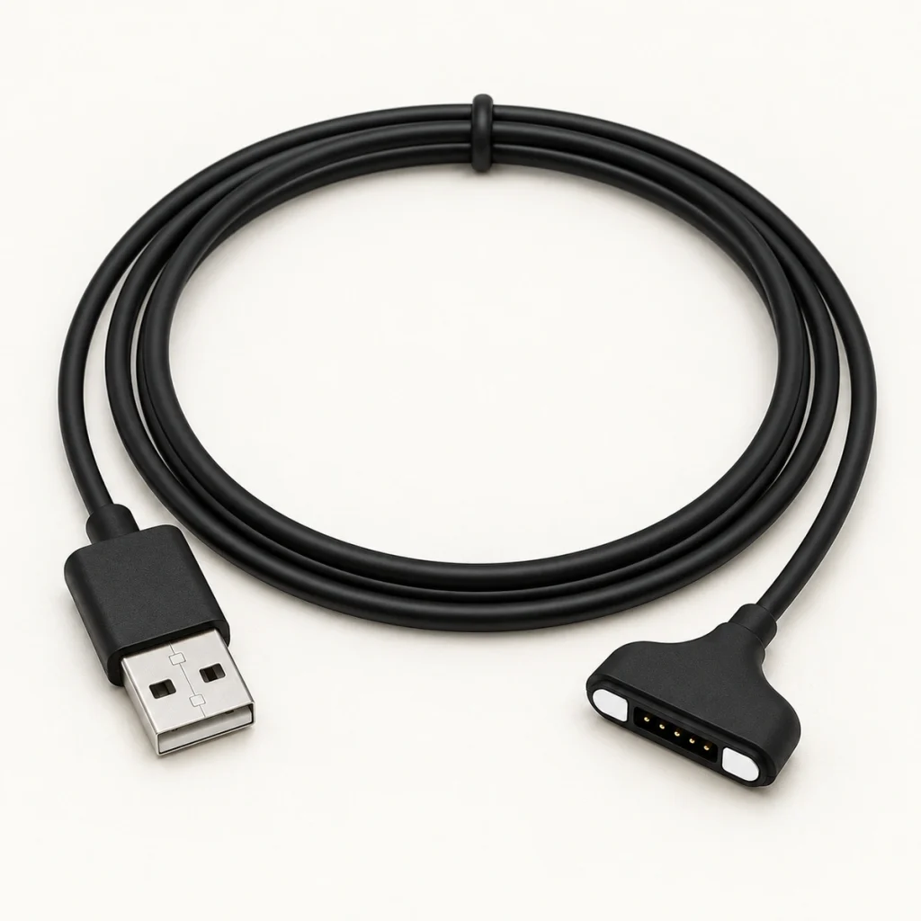
A straight exit, described here as 180°, can suit open mounting space, docks, test equipment, robots or handheld terminals. Compare the actual route and clearances for the assembly.
The straight structure generally offers:
Direct cable routing
Easier assembly in open housings
Simpler cable replacement
Clearer strain direction
Convenient connection to desktop charging bases
Choose the exit from the housing drawing and expected cable movement, rather than appearance alone.
Board and Housing Integration
A correct wire assignment is only part of reliable contact. Integrate both mating halves with the PCB and housing so the mechanical stack maintains their electrical connection.
magnetic connectorEngineers should review:
Working height
After mating, each pogo contact should remain within its specified compression range. Too little compression can allow dropouts; too much can damage the spring or housing.
Coplanarity
Account for pin-height variation, PCB warp, housing deformation and assembly tolerances. All five contacts must seat as intended; a signal can remain open even while the power contacts conduct.
Magnetic force
Set enough retention for normal device movement without making release unnecessarily difficult or overloading the board, cable or mounting structure.
Mounting method
Possible structures include:
SMT mounting
THT / through-hole electrical termination
Wire-solder connection
Embedded housing installation
Panel mounting
Overmolded cable assembly
Choose the mounting combination around assembly methods, board area, operating loads and the sealing plan.
Sealing the Rear and Cable Exit
Sealing only the contact face is insufficient. Water can reach the rear joints, cable exit, plastic-to-metal boundary, mounting opening or the interface between the connector and enclosure.
Depending on the project, the sealing structure may include:
Rear adhesive sealing
Potting compound
O-ring
- Gasket
Overmolded cable head
Sealed mounting recess
Waterproof housing interface
Verify IP65, IP67 or IP68 targets on the complete installed assembly. A rated connector component does not automatically give the finished device the same protection.
Define sealing requirements before finalizing the enclosure and cable tooling. Seal features can alter connector dimensions and installation clearances.
Designing Against Corrosion
Sweat, humidity, salt mist, cleaning chemicals and condensation can affect contacts in wearable, outdoor, medical or industrial products, raising resistance or interrupting charging and data. Match protection to the actual exposure.
The engineering review should consider:
Contact base material
Gold or composite plating
Plating thickness
Nickel barrier layer
Magnet corrosion protection
Plastic material
Drainage and cleaning access
Mated and unmated exposure
Required salt-spray duration
Relevant verification includes plating-thickness checks, salt spray, controlled temperature-and-humidity exposure, microscopy and resistance measurements before and after environmental tests.
A desktop interface, pet tracker, medical wearable and outdoor sensor face different exposure. Select the contact finish and protective structure for the actual environment.
Documenting Cable Colors
Colors assist assembly, but the approved pinout remains the authority. The table gives one possible custom cable color scheme:
| Wire Color | Possible Function |
|---|---|
| Red | Power |
| Black | Ground |
| White | Data or signal |
| Green | Data or signal |
| Yellow | Detection or control |
Scroll horizontally to view every column.
This color scheme is an example only. Other factories, cables and projects may assign different colors.
The approved cable drawing should include:
Pin number
Wire color
Wire gauge
Cable length
Terminal type
Shielding requirement
Continuity definition
Cable outlet direction
Connector part number
Tolerance
Production continuity checks should cover all five assigned paths and detect shorts between neighboring contacts. Contact count does not imply five independent complete circuits.
Prototype Verification
Complete both electrical and mechanical verification before releasing a custom five-contact cable assembly for production. Agree test conditions and acceptance criteria for the project.
| Test | Purpose |
|---|---|
| Dimension inspection | Confirm pitch, height, housing and mounting dimensions |
| Pin-height inspection | Verify consistent compression across five contacts |
| Continuity test | Confirm pin-to-wire and male-to-female mapping |
| Short-circuit test | Detect bridging or wiring errors |
| Contact-resistance test | Evaluate electrical stability |
| Current and temperature-rise test | Confirm power-contact capability |
| Signal-function test | Verify communication in the actual device |
| Magnetic polarity test | Verify the intended polarity and orientation |
| Magnetic-force test | Confirm holding and removal behavior |
| Cable bending test | Evaluate the 90° or 180° cable outlet |
| Pull test | Check soldering and overmold retention |
| Mating-cycle test | Evaluate contact wear |
| Salt-spray test | Assess corrosion resistance |
| Waterproof test | Validate the installed sealing structure |
| Final-device test | Confirm operation inside the real housing |
Scroll horizontally to view every column.
Where possible, evaluate the sample in the intended board and enclosure. A part that passes isolated tests can still fail due to mounting-height tolerances, housing fit, cable clearance or firmware timing.
Application Examples
Consider five contacts where charging must share an interface with one or more auxiliary functions.
Typical applications include:
Smartwatches and fitness trackers
Smart rings and wearable charging docks
Behind-the-ear electronic devices
Portable medical electronics
Smart locks and removable control modules
POS terminals and barcode scanners
Industrial tablets
Pet trackers
Smart mugs and heated cup bases
Test equipment
Robots and sensor modules
Portable consumer electronics
Five contacts can allocate power, return, detection, ID, data or control in a custom geometry. Compare the enclosure integration with a conventional USB opening; the interface still needs its own approved mounting and sealing structure.
Inputs for a Custom Cable Drawing
Provide these inputs when developing a custom five-contact assignment:
Device application
Housing drawing or 3D model
Available connector dimensions
PCB layout
Required pin assignment
Current and voltage
Signal type and data rate
Mounting method
Desired magnetic force
90° or 180° cable direction
Cable length
Wire gauge
Cable-end connector
Waterproof requirement
Environmental exposure
Sample quantity
Estimated production volume
Use these inputs to review structure, contact arrangement, wiring, plating, polarity and sealing before approving samples.
Wiring Design Questions
Is There a Universal Five-contact Assignment?
No. The device circuit determines how the five contacts carry power, return, data, detection, ID or control. Confirm the approved mating-face views and wire definitions for the actual pair.
What Is Required to Carry Power and Data Together?
Evaluate contact layout, cable construction, signal type, ground paths, current load and connector geometry for the application. Higher-speed communication may require additional signal-integrity testing.
What Must Be Checked Before Paralleling Contacts?
Parallel power or return contacts need current-sharing assessment across resistance, spring force, compression, board routing and cable construction. Verify temperature rise and voltage drop; do not simply add nominal contact ratings.
Which Roles Can the Fifth Contact Have?
Detection, identification, control, temperature sensing or another data path are possible roles. Define one appropriate function or a supported circuit arrangement for the device.
Does the Cable Exit Determine the Pinout?
No fixed change is required. A 90° and a 180° exit can share an assignment while differing in exit direction, overmold, bend radius and installation space. Confirm each assembly drawing.
How Is Sealing Performance Established?
A custom structure can be developed toward IP65, IP67 or IP68 requirements. Rear seals, overmolding, enclosure installation and gasket design must be evaluated by complete-device testing.
Releasing a Documented Design
Begin with the circuit and mechanical stack, rather than a generic cable color scheme. Before releasing drawings, define current paths, signals, detection logic, mapping between both halves, mounting height, retention, cable route and environmental exposure.
A suitable five-contact pogo interface can combine charging, data, ID and control while easing alignment and limiting insertion wear. A 90° or 180° cable may use the same pinout, but its clearance, strain relief and installation direction still need validation inside the final enclosure.